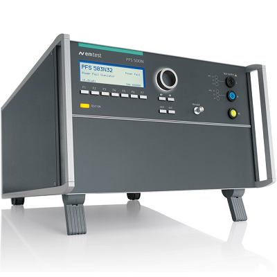
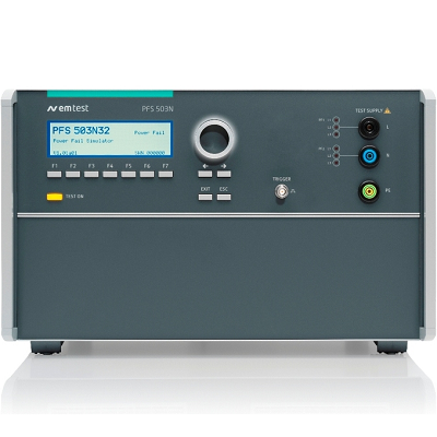
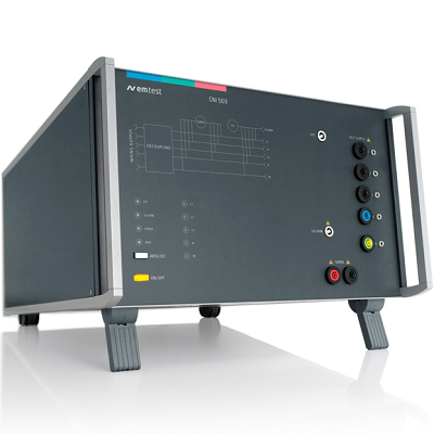
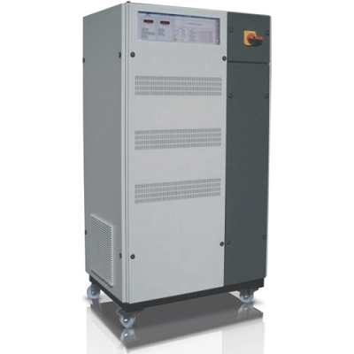
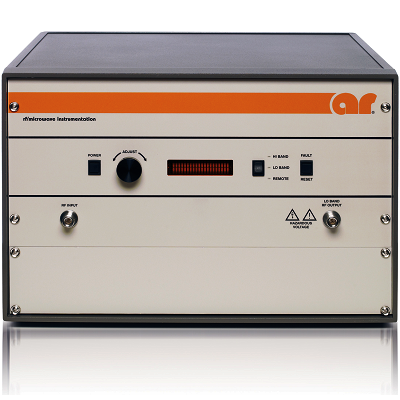
EM TEST PFS 503N100 Power Fail Simulator
Description
EM TEST PFS 503N100 Power Fail Simulator for Dips, Short Interruptions and Voltage Variations as per IEC 61000-4-11 and IEC 61000-4-34
EM TEST PFS 503N100 Power Fail Simulator represents a real three-phase simulator. Not only phase-by-phase testing is possible, but any combination of phases as well as all three phases can be simultaneously tested. Therefore, the PFS 503N100 is equipped with six individually controlled semiconductor switches. Each switch is electronically short-circuited protected.
The PFS 503N100 has BNC outputs for individual current monitoring for each phase by means of an oscilloscope. The inrush current can be measured using these BNC outputs. An analog DC signal of 0 to 10V is supplied to drive an external motorized three-phase variac. The PFS 503 can also be used for single phase testing offering a separate DUT output for this purpose.
MODEL SERIES OVERVIEW
PFS 503N-series Simulator for Dips, Short Interruptions and Voltage Variations
Features
- Standalone test generator for dips, short interruptions and voltage variation
- Full-compliant three-phase system as per IEC 61000-4-11, Ed.2:2004 and IEC 61000-4-34 for testing delta and star supply systems
- 6 electronic switches, short-circuit protected
- Rated voltage up to 3x690V AC, 600V DC
- Nominal current up to 100A per phase
- DC signal to control external variac
- Front panel operation
- Standard Test routines
- USB and GPIB interfaces
Specifications
| MODEL CONFIGURATION | |
| PFS 503N100 | 3x480V AC, max. 100A per phase 277V AC (L-N), 360V DC |
| POWER SWITCHES | |
| Three-phase application | |
| Voltage (L-L) | 3x480V AC resp. 3x690V AC |
| Frequency | 50Hz/60Hz |
| Single phase application | |
| Voltage(L-N) | 277V AC resp. 400V AC
360V DC resp. 600V DC |
| Frequency | 50Hz/60Hz and DC |
| Current AC/DC | Max. 100A |
| Peak current | Better than 1,000A |
| Fall/rise time | Between 1us and 5us for abrupt changes, generator loaded with resistive load |
| Switches are electronically protected against short-circuit | |
| OUTPUTS | |
| 3-Phase application | L1, L2, L3, N and PE on the rear panel |
| 1-Phase application | L, N and PE on the front panel |
| TECHNICAL DATA | |
| INTERFACES | |
| Serial | USB |
| Parallel | IEEE 488, addresses 1 to 30 |
| Analog output | 0 to 10 V DC to control an external motor variac |
| GENERAL DATA | |
| Dimensions | 19″/6 HU |
| Weight | approx. 28kg |
| Supply voltage | 115V/230V +10/-15% |
| Fuses | 2 x T 1A (230V) or 2 x T 2A (115V) |
