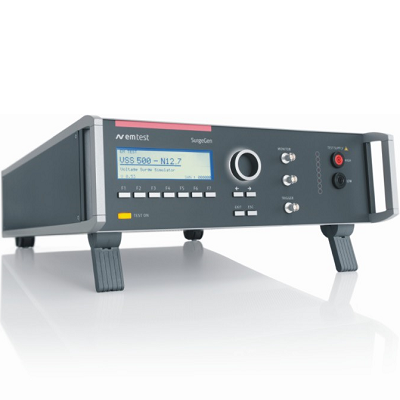
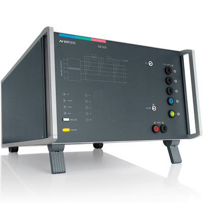
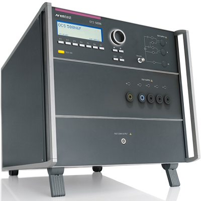
EM TEST OCS 500N6F.3 Oscillatory Wave Simulator
Description
EM TEST OCS 500N6F.3 Simulator for Fast and Slow Damped Oscillatory Waves and Ringwave
EM TEST OCS 500N6F.3 includes test capabilities for fast damped oscillatory waves at 3 MHz, 10 MHz and 30 MHz up to 4.4kV and is extendable for slow damped oscillatory waves at 100 kHz / 1 MHz up to 3.0 kV as per IEC/EN 61000-4-18 and for ringwave up to 6 kV as per IEC/EN 61000-4-12.
The OCS 500N6F.3 comes with a built-in coupling/decoupling network for either single phase or three-phase and is rated for currents of 16 A or 32 A per line.
MODEL SERIES OVERVIEW
OCS 500N6F-series Compact Simulators for Fast/Slow Damped Oscillatory Waves and Ringwave
Features
- Fully automated single box test system
- Single DUT port
- Fast Damped Oscillatory Waves up to 4.4 kV
- Slow Damped Oscillatory Waves up to 3 kV (option)
- Ringwave up to 6 kV (option)
- Built-in CDN, 1-phase or 3-phase up to 32 A
- Front panel operation
- USB and GPIB interfaces
Specifications
| MODEL OVERVIEW | |
| OCS 500N6F.3 | AC 3×440 V / 16 A, DC 250 V / 32 A |
| FAST DAMPED OSCILLATORY MODULE | |
| FAST DAMPED OSCILLATORY WAVES AS PER IEC/EN 61000-4-18 | |
| Voltage (o.c.) at HV output | 450 V – 4,400 V ±10% |
| Rise time | 5 ns ±30% |
| Oscillation frequencies | 3 MHz, 10 MHz and 30 MHz, ±10% |
| Decaying | Peak 5 to be > 50% of peak 1 value
Peak 10 to be < 50% of peak 1 value |
| Source impedance | 50 ohms ±20% |
| Coupling | common mode |
| Polarity | Positive, negative |
| Repetition rate | Max. 5,000 /s ±10% |
| Burst duration | 50 ms ±20%, at 3 MHz
15 ms ±20%, at 10 MHz 5 ms ±20%, at 30 MHz |
| Burst period | 300 ms ±20% |
| Short-circuit current | 9 A – 88 A ±20% |
| Rise time current waveform | < 330 ns at 3 MHz
< 100 ns at 10 MHz < 33 ns at 30 MHz |
| Decaying (current) | Peak 5 to be > 25% of peak 1 value
Peak 10 to be < 25% of peak 1 value |
| GENERAL SPECIFICATIONS | |
| OUTPUT | |
| Direct | Via HV-safety lab connectors |
| Coupling mode | Line to line Line(s) to ground (PE) |
| DUT supply | |
| OCS 500N6F.3 | AC: 3×440 V / 32 A; 50/60 Hz
DC: 250 V / 32 A |
| CRO trigger | 5V trigger signal for oscilloscope |
| MEASUREMENTS | |
| Ring wave | Peak voltage and peak current in LCD |
| GENERAL DATA | |
| INTERFACE | |
| Optical interface | Opto link, 3 m cable USB A connector |
| Parallel interface | IEEE 488, addresses 1 – 30 |
| GENERAL DATA | |
| Dimensions, weight | 19″ / 9 HU, approx. 50 kg |
| Supply voltage | 115/230 V +10/-15% |
| Fuses | 2 x T2AT (230V); 2 x T4AT (115V) |