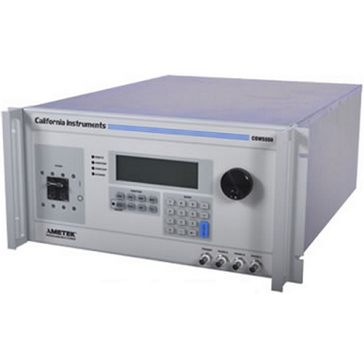
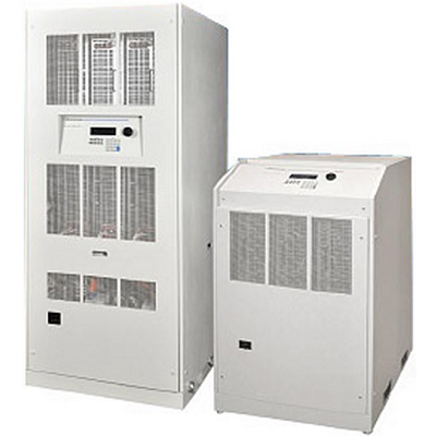
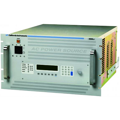
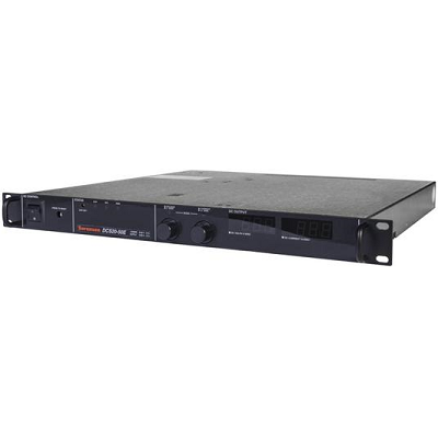
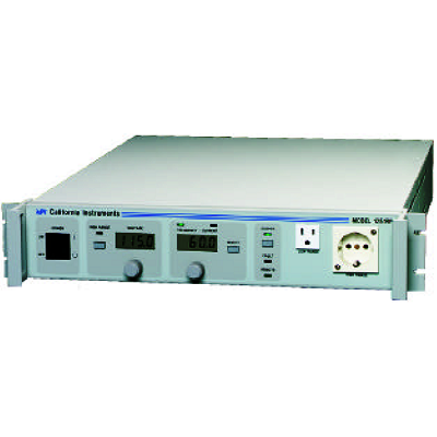
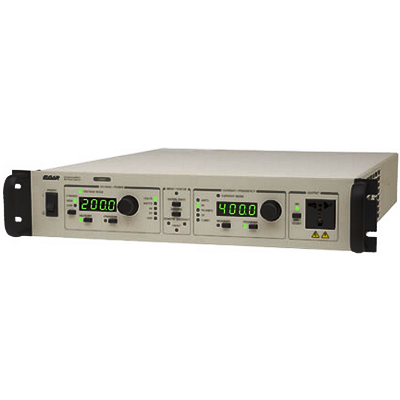
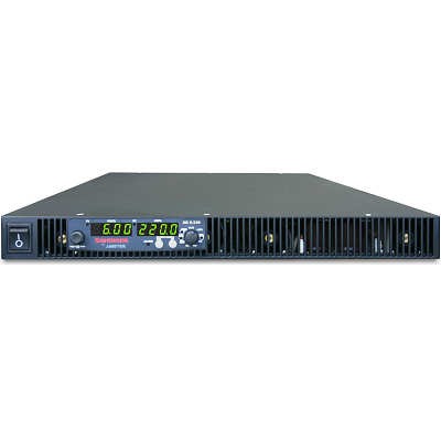
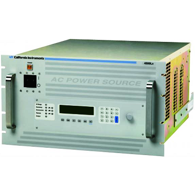
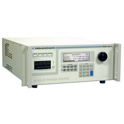
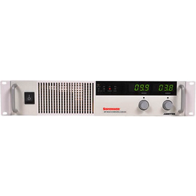
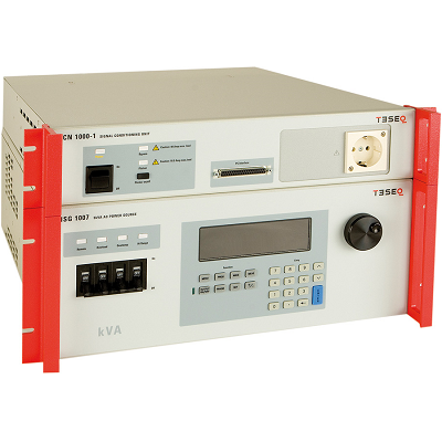
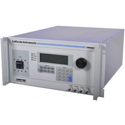
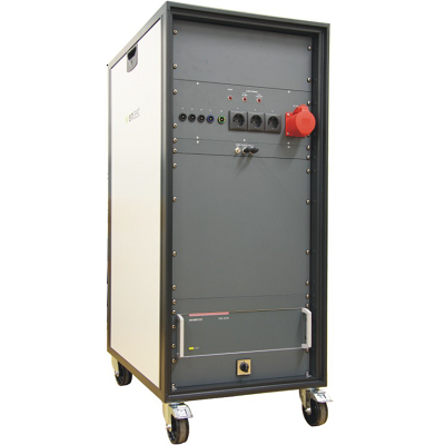
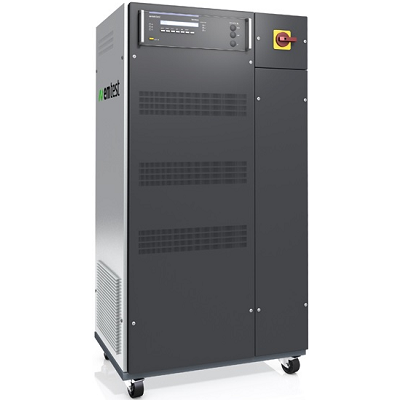
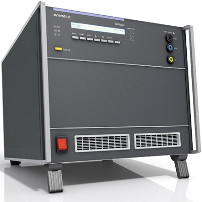
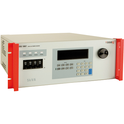
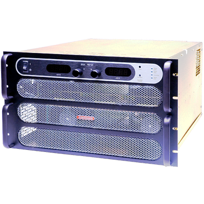
California Instruments CSW44400 Programmable AC Power Source 44.4kVA
Description
The CSW Series represents a new generation of AC/DC power sources that address the increasing demands on test equipment to perform additional functions at a lower cost. By combining a flexible AC/DC power source with a high performance power analyzer, the Compact CSW Series is capable of handling complex applications that have traditionally required multiple systems. The sleek integrated approach of the CSW avoids cable clutter that is commonly found in test systems. All connections are made internally and the need for digital multimeters, power harmonics analyzers, and current shunts or clamps is eliminated.
Since many components in the CSW are shared between the AC/DC source and the power analyzer, the total cost of the integrated system is less than the typical cost of a multiple unit system.
Features
- Combination AC and DC Power Source
- 40-5,000Hz Output Frequencies
- Arbitrary and Harmonic Waveform Generation
- Built-In Digital Power Analyzer
- Scope Capture Capability
- Power Programming Software
- Constant Power Mode
- Multi-Box Option
California Instruments CSW44400 Applications
- Avionics
- Telecommunications
- Commercial Electronics
- Testing for real world power conditions using different waveforms on all 3 phases (including DC)
- Load susceptibility testing with sequence or event programming and multiple voltage harmonics
- Power line disturbance simulation testing
- MIL-STD-704, DO-160, B747 and ABD100 avionics testing
- Power supply testing for AC-DC, DC-DC converters and UPS's
- Transients on 12 & 24 VDC for automotive applications
Specifications
|
Input |
||||||
|
Voltage Ranges |
Factory configured 187 to 264 Vrms, 3ø L-L (3 wire), or 342 to 457 Vrms, 3ø L-L (4 wire). A chassis ground is also required. |
|||||
|
Power Factor |
PFC Input, 0.99PF |
|||||
|
Frequency Range |
47 to 440 Hz |
|||||
|
Efficiency |
70% min, at full load |
|||||
|
Ride Through |
70% min, at full load |
|||||
|
Output |
||||||
|
Power |
5550 VA: 1ø or 3ø (systems up to 33,000 VA) |
|||||
|
AC or DC Output Voltage |
0 to156 Vrms L-N, low range; 0 to 312 Vrms L-N, high range |
|||||
|
Current Per Phase |
13/16A to 135V in 156V range; 6.5/13A to 270V in 312V range per 1750/1850 VA module. |
|||||
|
Power Factor of Load |
0 lagging to 0 leading (0-unity) |
|||||
|
Crest Factor |
3.25:1 (peak output current to rms output current) |
|||||
|
Frequency Range |
Specifications apply DC, 40Hz to 5kHz. For output frequencies greater than 1 kHz, the max slew rate allowed is 1 kHz per second. |
|||||
|
Max Total Harmonic Distortion |
(Full Linear Load or No Load): 0.25% max, 40 to 100 Hz; 0.5% max to 500 Hz; and 1% max to 1 kHz plus 1%/kHz to 5 kHz |
|||||
|
AC Noise Level |
>60 dB rms below full output voltage |
|||||
|
Amplitude Stability |
±0.1% of full scale over 24 hours at constant line, load and temperature |
|||||
|
Line Regulation |
(DC, or 40 Hz to 5 kHz): ±0.015% of full scale for a ±10% input line change |
|||||
|
Load Regulation |
±0.025% of full scale voltage for a full resistive load to no load; above 1 kHz, add ±0%/kHz |
|||||
|
Voltage Accuracy |
±0.1% of range. Above 1 kHz, add 0.2%/kHz. Add ±0.1% of full scale for “AC PLUS DC” mode. Valid for 5 to 156 Vrms and 10 to 312 Vrms at 25°C |
|||||
|
Voltage Resolution |
1mV (0.1V) Full Scale |
|||||
|
Frequency Accuracy |
±0.01% at 25°C ±0.001%/°C |
|||||
|
Frequency Resolution |
40 Hz to 81.91 Hz (0.01 Hz) |
|||||
|
Phase Accuracy, |
±1% of Programmed value |
|||||
|
Phase Angle Resolution |
0.1° |
|||||
|
Remote Output Voltage Sense |
5 Vrms total lead drop, max |
|||||
|
Common |
||||||
|
Standard Features |
• 1ø to 3ø programmable |
|||||
|
Interface |
IEEE-488.2 interface, RS232, USB, Optional LAN |
|||||
|
Protocol |
SCPI protocol |
|||||
|
WaveForm trigger output |
(1 MΩLoad Drive) |
|||||
|
Sync OUT |
User programmed for: Cycle start, all cycles. Segment start, all or selected segments. For loads ≥2 kΩ: V out ≤1V low state; V out ≥2.4V high state |
|||||
|
Clock/lock |
Clock – pulses at programmed frequency. For loads ≥2 kΩV out: ≤1V low state; V out ≥2.4V high state Lock – locks output to input 'TTL' frequency; signal needs to supply pull down current of 15 mA with voltage drop of ≤0.6V; no pull up needed |
|||||
|
External Amplitude Modulation |
0 to 5 Vrms provides 0 to ≥20% output amplitude modulation |
|||||
|
External Drive |
Normal amplifier, 0 to 5 Vrms (DC to 5 kHz) or ±5 VDC input for zero to full voltage output |
|||||
|
External Gain Control |
0 to ±7.07 VDC provides zero to full output |
|||||
|
External Input Impedance |
≥30 kΩ |
|||||
|
Environmental |
||||||
|
Operating Temperature |
0°C to 45°C (32°F to 113°F) |
|||||
|
Storage Temperature |
-40°C to 70°C (-40°F to 158°F) |
|||||
|
Cooling |
Air is drawn in from the top, bottom, and sides and exhausted through the rear |
|||||
|
Humidity (Non-condensing) |
0 to 85% at 25°C (77°F); derate to 50% at 40°C (104°F) |
|||||
|
Altitude |
Operating 10,000 ft, non operating 40,000 ft |
|||||
|
Physical |
||||||
|
Dimensions |
Width: 19″ (483 mm) |
|||||
|
Weight |
CSW 5550 – 127 lbs (57.5 kg) |
|||||
|
Shipping Weight – US |
CSW – 200 lbs (91 kg) |
|||||
|
Note: Multi Chassis systems, dimension and weight are approximately x2, x3 and x4 CSW Specifications |
||||||
|
Measurements – Standard (AC Measurements) |
||||||
|
Parameter |
Frequency |
Phase |
Voltage (AC rms) |
Current (AC rms) |
||
|
Range |
40-81.91 Hz |
40-100 Hz |
0-300 V |
0-50 A |
||
|
Accuracy* (±) |
0.1% + 1 digit |
0.5° |
0.5% + 250 mV |
0.1% + 150 mA |
||
|
Accuracy* (±) |
.01 Hz / 0.1 Hz / 1 Hz |
2° |
0.5% + 250 mV |
0.1% + 50 mA |
||
|
Resolution* |
.01 Hz / 0.1 Hz / 1 Hz |
0.1° / 1° |
10 mV |
1 mA |
||
|
Parameter |
Real Power |
Apparent Power |
Power Factor |
|||
|
Range |
0-6 kW |
0-6 kVA |
0.00-1.00 |
|||
|
Accuracy* (±) 1 ø mode (-1) |
0.15% + 9 W |
0.15% + 9 VA |
0.03 |
|||
|
Accuracy* (±) 3 ø mode (-3) |
0.15% + 3 W |
0.15% + 3 VA |
0.01 |
|||
|
Resolution* |
1 W |
1 VA |
0.01 |
|||
|
* Accuracy specifications are in % of reading and apply above 100 counts. For multi-chassis configurations, current, power range and accuracy specifications are times three. Power factor accuracy applies for PF > 0.5 and VA > 50% of max. Frequency measurement specification valid for output > 30 Vrms. |
||||||
|
Harmonic Measurements |
||||||
|
Parameter |
Range |
Accuracy ( ± ) |
Resolution |
|||
|
Frequency fundamental |
16.00 – 1000 Hz |
2 counts |
0.01 Hz to 1 Hz |
|||
|
Frequency harmonics |
32.00 Hz – 16 kHz |
2º typ. |
0.5º |
|||
|
Voltage |
Fundamental |
0.25V |
0.01V |
|||
|
Harmonic 2 – 50 |
0.25V + 0.1% + 0.1%/kHz |
0.01V |
||||
|
Current |
Fundamental |
0.05A |
0.01A |
|||
|
Harmonic 2 – 50 |
0.05A + 0.1% + 0.1%/kHz |
0.01A |
||||
|
Harmonics frequency range in three-phase mode is 32 Hz – 16 kHz. Accuracy specifications are multiplied by the number of power sources in multi-source systems with the 3-phase (3Ø) or the number of sources times 3 in the 1-phase (1Ø) mode. Measurement bandwidth is limited to 16 Khz. |
||||||
|
Model |
CSW5550 |
CSW11100 |
CSW16650 |
CSW22200 |
||
|
Multiplier 3Ø/1 Ø |
1/3 |
2/6 |
3/9 |
4/12 |
||
|
Model |
CSW17750 |
CSW33300 |
CSW38850 |
CSW44400 |
||
|
Multiplier 3Ø/1 Ø |
5/15 |
6/18 |
7/21 |
8/24 |
||
|
Protection And Safety |
||||||
|
Overvoltage Shutdown |
Programmable for 15V to 255V peak, 156V range; 30V to 510V peak, 312V range |
|||||
|
Programmable Current Limit Shutdown |
Settable to 0.01 ARMS Resolution |
|||||
|
Programmable Current Limit |
Settable to 1% of range: the timeout is settable from 100 ms to 10s. |
|||||
|
Over temperature Shutdown |
Automatic, not programmable |
|||||
|
Regulatory Compliance |
• EN 61010 |
|||||
