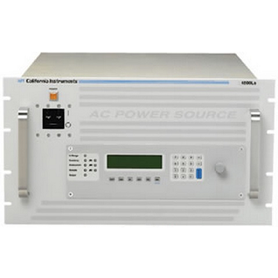
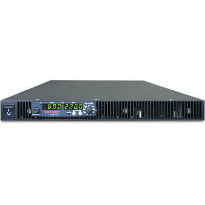
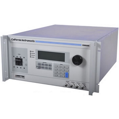
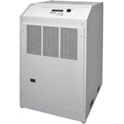
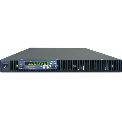
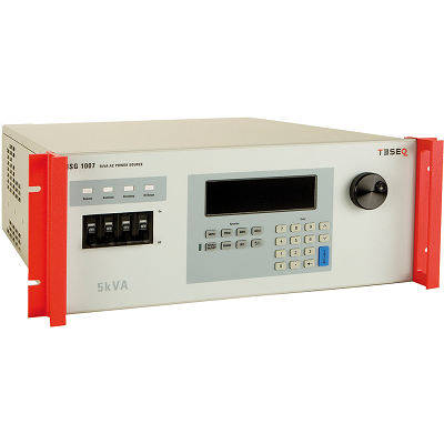
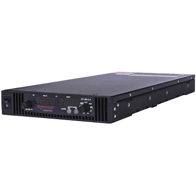
California Instruments 6000Ls Programmable AC Power Source 6kVA
Description
The Ls/Lx Series is a completely improved new product based on the popular California Instruments L Series. Both the Ls and Lx feature many basic AC Source capabilities at a very reasonable price. For more information on either product, please click on the product tab on the right.
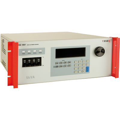
The Ls Series is an improved version of the classic California Instruments L Series AC power sources. It provides many basic AC source capabilities at an economical cost. Additional capabilities such as arbitrary waveform generation and harmonic measurements can be added as options. The Ls Series can be ordered in either single phase (-1) or three phase (-3) configurations. Power levels range from 3 kVA to 6 kVA in a single chassis. Multiple chassis can be combined for power levels up to 18 kVA. The Ls Series is completely microprocessor controlled and can be operated from a simple front panel keypad. A pair of analog controls located next to the backlit alphanumeric LCD display allows output voltage and frequency to be slewed up or down dynamically. For more advanced operations, a series of menus is provided using a dual line high contrast LCD display. The Lx Series represents a modern AC power source that addresses increasing demands on test equipment to perform more functions at a lower cost. By combining a flexible AC power source with a high-end harmonic power analyzer, the Lx Series systems are capable of handling applications that would traditionally have required multiple instruments.
Features
- Backward Compatible with L Series – Function and bus compatible with the California Instruments L Series
- Three phase and Single phase modes – Ideally suited for avionics and defense applications
- 3 KVA to 18 KVA Power Levels – Match power source and cost to application requirements
- Transient Programming – Test products for susceptibility to AC line disturbances
- Built-in Measurements – Performs voltage, current, and power measurements
- Advanced Features – Arbitrary waveform generation, harmonic analysis, GPIB interface are some of the available options
- Interface – Standard USB & RS232C interface. (Optional GPIB & LAN available)
- CE Marked (400V input model ONLY) – Safe, reliable, and consistent operation
Specifications
|
Output Ls |
|||||||||
|
Maximum Power per phase |
3000Ls: 1 phase 3000 VA, 3 phase 1000 VA; |
||||||||
|
Power factor |
0 to unity at full output VA |
||||||||
|
Voltage Ranges |
|||||||||
|
Range |
VLow |
VHigh |
|||||||
|
AC |
0 – 135 V |
0 – 270 V |
|||||||
|
VA Programming Resolution |
100 mV |
||||||||
|
Load Regulation |
< 0.1 % FS |
||||||||
|
Line Regulation |
< 0.02 % for 10 % line change |
||||||||
|
See -HV and EHV options for alternative voltage range pairs. |
|||||||||
|
Programming Accuracy |
Voltage (rms): ± (0.05% + 0.25) V from 5.0 V to FS; Frequency: |
||||||||
|
Frequency Range |
45 Hz – 1000 Hz (see -HF option for higher output frequencies) |
||||||||
|
Frequency Resolution |
0.01 Hz at < 81.9 Hz, |
||||||||
|
Max RMS Current at Low V range |
|||||||||
|
At Full Power |
|||||||||
|
Model |
1 ø |
3 ø |
|||||||
|
3000Ls |
44.4 A |
14.8 A |
|||||||
|
4500Ls |
44.4 A |
14.8 A |
|||||||
|
6000Ls |
44.4 A |
14.8 A |
|||||||
|
At Full Scale Voltage |
|||||||||
|
Model |
1 ø |
3 ø |
|||||||
|
3000Ls |
22.2 A |
7.4 A |
|||||||
|
4500Ls |
33.3 A |
11.1 A |
|||||||
|
6000Ls |
44.4 A |
14.8 A |
|||||||
|
Note: Constant power mode on 3000Ls and 4500Ls provides increased current at reduced voltage; |
|||||||||
|
Current Limit |
Programmable from 0 Amps to maximum current for selected range |
||||||||
|
Peak Current |
3000Ls: 6 X (lrms @ full scale voltage); 4500Ls: 4 X (lrms @ full scale voltage); 6000Ls: 3 X (lrms @ full scale voltage) |
||||||||
|
Output Noise |
100mV rms typ. (20 kHz to 1 MHz) – Standard |
||||||||
|
Harmonic Distortion |
< 1% (at full scale voltage, full resistive load) |
||||||||
|
Output Relay |
Push button controlled and bus controlled output relay |
||||||||
|
Output Lx |
|||||||||
|
Maximum Power per phase |
3000Lx: 1 phase: 3000 VA, 3 phase: 1000 VA; |
||||||||
|
Power factor |
0 to unity at full output VA |
||||||||
|
Voltage Ranges |
|||||||||
|
Range |
VLow |
VHigh |
|||||||
|
AC |
0 – 150 V |
0 – 300 V |
|||||||
|
VA Programming Resolution |
100 mV |
||||||||
|
Load Regulation |
< 0.1 % FS ALC On or Reg. |
||||||||
|
Line Regulation |
< 0.02 % for 10 % line change |
||||||||
|
See -HV and EHV options for alternative voltage range pairs. |
|||||||||
|
Programming Accuracy |
Voltage (rms): ± (0.05% + 0.25) V from 5.0 V to FS, ALC On or Reg; |
||||||||
|
Frequency Range |
45 Hz – 1000 Hz (see -HF option for higher output frequencies) (Derated voltage from 17 Hz – 45Hz) |
||||||||
|
Frequency Resolution |
0.01 Hz at < 81.9 Hz, |
||||||||
|
Max RMS Current at Low V range |
|||||||||
|
Phases V Range |
VLow |
VHigh |
|||||||
|
All 3 ø |
12.8 A |
6.4 A |
|||||||
|
models 1 ø |
38.4 A |
19.2 A |
|||||||
|
At Full Scale Voltage |
|||||||||
|
Model |
VLow |
VHigh |
|||||||
|
3000Lx 3 ø |
6.6 A |
3.3 A |
|||||||
|
3000Lx 1 ø |
20.0 A |
10.0 A |
|||||||
|
4500Lx 3 ø |
10.0 A |
5.0 A |
|||||||
|
4500Lx 1 ø |
30.0 A |
15.0 A |
|||||||
|
6000Lx 3 ø |
12.8 A |
6.4 A |
|||||||
|
6000Lx 1 ø |
38.4 A |
19.2 A |
|||||||
|
Note: Constant power mode on 3000Lx and 4500Lx provides increased current at reduced voltage; 6000Lx provides maximum power output. |
|||||||||
|
Current Limit |
Programmable from 0 Amps to maximum current for selected range |
||||||||
|
Peak Current |
3000Lx: 5.7 X (lrms @ full scale voltage); 4500Lx: 3.8 X (lrms @ full scale voltage); 6000Lx: 3 X (lrms @ full scale voltage) |
||||||||
|
Output Noise |
100mV rms typ. |
||||||||
|
Harmonic Distortion |
< 1% (at full scale voltage, full resistive load) |
||||||||
|
Output Relay |
Push button controlled and bus controlled output relay |
||||||||
|
Input Ls |
|||||||||
|
Voltage |
Models 3000Ls, 4500Ls, 9000Ls, 13500Ls: Standard: 208-230 ± 10% VAC, (L-L, 3 Phase); Option -400: 400 ± 10% VAC (L-L, 3 Phase) Includes CE Mark; Models 6000Ls, 12000Ls, 18000Ls: Standard 208-230 + 10% VAC (L-L, 3 Phase) Notes: 1. Input must be specified when ordering. 2. -400 option not availble on 6000Ls, 12000Ls, 18000Ls. 3. 3000Ls can be operated from 1 phase AC. 4. -480V option ± 5% VAC (L-L, 3 Phase) available on 3000Ls & 4500 Ls (3 phase output only) |
||||||||
|
Line Current (rms per phase) |
|||||||||
|
Model |
187 VLL |
187 VLN (1 ø) |
208 VLL |
360 VLL |
|||||
|
3000Ls |
19 A |
32 A |
n/a |
10 A |
|||||
|
4500Ls |
31 A |
n/a |
n/a |
16 A |
|||||
|
6000Ls |
n/a |
n/a |
38 A |
n/a |
|||||
|
Inrush Current (Per phase) |
@ 180-254 V: 50 A peak |
||||||||
|
Line Frequency |
47-440 Hz |
||||||||
|
Efficiency |
80% typical |
||||||||
|
Power Factor |
0.7 typical |
||||||||
|
Hold-up Time |
At least 10 ms |
||||||||
|
Input Lx |
|||||||||
|
Voltage |
ModeLx 3000Lx, 4500Lx, 9000Lx, 13500Lx: Standard: 208-230 ± 10% VAC, (L-L, 3 Phase); Option -400: 400 ± 10% VAC (L-L, 3 Phase) Includes CE Mark; ModeLx 6000Lx, 12000Lx, 18000Lx: Standard 208-230 + 10% VAC (L-L, 3 Phase) Notes: 1. Input must be specified when ordering. 2. -400 option not available on 6000Lx, 12000Lx, 18000Lx. 3. 3000Lx can be operated from 1 phase AC. |
||||||||
|
Line Current (rms per phase) |
|||||||||
|
Model |
3000Lx |
3000Lx (1Phase) |
4500Lx |
6000Lx (@ 280V) |
|||||
|
187 VLL |
19 A |
32 A |
31 A |
38 A |
|||||
|
360 VLL |
10 A |
n/a |
16 A |
n/a |
|||||
|
Inrush Current (Per phase) |
@ 180-254 V: 50 A peak |
||||||||
|
Line Frequency |
47-440 Hz |
||||||||
|
Efficiency |
80% typical |
||||||||
|
Power Factor |
0.7 typical |
||||||||
|
Hold-up Time |
At least 10 ms |
||||||||
|
Ls Measurements – Standard (AC Measurements) |
|||||||||
|
Parameter |
Frequency |
Phase |
Voltage (AC rms) |
Current (AC rms) |
|||||
|
Range |
45-1000Hz |
45-100Hz |
0-400V |
0-50A |
|||||
|
Accuracy* (±) |
0.1% + 1 digit |
0.5° |
0.05% + 250 mV |
0.1% + 150 mA |
|||||
|
Accuracy* (±) |
0.1% + 1 digit |
0.5° |
0.05% + 250 mV |
0.1% + 50 mA |
|||||
|
Resolution* |
0.01 Hz / |
0.1° |
10 mV |
1 mA |
|||||
|
Parameter |
Real Power |
Apparent Power |
Power Factor |
||||||
|
Range |
0-6kW |
0-6kVA |
0.00-1.00 |
||||||
|
Accuracy* (±) 1 ø mode (-1) |
0.15% + 9 W |
0.15% + 9 VA |
0.03 |
||||||
|
Accuracy* (±) 3 ø mode (-3) |
0.15% + 3 W |
0.15% + 3 VA |
0.01 |
||||||
|
Resolution* |
1 W |
1 VA |
0.01 |
||||||
|
* Accuracy specifications are in % of reading and apply above 100 counts. For multi-chassis configurations, current, power range and accuracy specifications are multiplied by 3. Power factor accuracy applies for PF > 0.5 and VA > 50% of max. Frequency measurement specification valid for output > 30 Vrms. |
|||||||||
|
Lx Measurements – Standard (AC Measurements) |
|||||||||
|
Parameter |
Frequency |
Phase |
Voltage (AC rms) |
Current (AC rms) |
|||||
|
Range |
45.00-81.91 Hz |
0.0° – 359.9° |
0-400V |
0-50A |
|||||
|
Accuracy* (±) |
0.1% + 1 digit |
0.5° < 100 Hz |
0.05% + 0.25V |
0.1% + 0.15A |
|||||
|
Accuracy* (±) |
0.1% + 1 digit |
0.5° < 100 Hz |
0.05% + 0.25V |
0.1% + 0.05A |
|||||
|
Resolution* |
0.01 Hz / |
0.1° / 1° |
10 mV |
1 mA |
|||||
|
Parameter |
Crest Factor |
Real Power |
Apparent Power |
Power Factor |
|||||
|
Range |
1.00 – 10.0 |
0-6kW |
0-6kVA |
0.00-1.00 |
|||||
|
Accuracy* (±) |
1.5% |
0.15% + 9 W |
0.15% + 9 VA |
0.03 |
|||||
|
Accuracy* (±) |
1.5% |
0.15% + 3 W |
0.15% + 3 VA |
0.01 |
|||||
|
Resolution* |
0.01 |
1 W |
1 VA |
0.01 |
|||||
|
* Accuracy specifications are in % of reading + scale error and apply above 100 counts. For multi-chassis configurations, current, power range and accuracy specifications are times three. CF accuracy applies for Irms > 50 % of max. PF accuracy applies for PF > 0.5 and VA > 50% of max. Frequency measurement specification valid for output > 20 Vrms. |
|||||||||
|
Ls System |
|||||||||
|
Storage |
Setup: 16 complete instrument setups / Transient List: 100 transient steps per list (SCPI mode) or 16 transient registers (APE mode) |
||||||||
|
Trigger Input/Output |
Input: Triggers measurements or transient steps – SMA connector: 10K pull-up / Output: SMA Connector: HCTTL output |
||||||||
|
Lx System |
|||||||||
|
Storage |
Setup: 16 complete instrument setups / Transient List: 100 transient steps per list (SCPI mode) |
||||||||
|
Trigger Input/Output |
Input: Triggers measurements or transient steps – SMA connector: 10K pull-up / Output: SMA Connector: HCTTL output |
||||||||
|
Ls Protection |
|||||||||
|
Storage |
Setup: 16 complete instrument setups / Transient List: 100 transient steps per list (SCPI mode) or 16 transient registers (APE mode) |
||||||||
|
Trigger Input/Output |
Input: Triggers measurements or transient steps – SMA connector: 10K pull-up / Output: SMA Connector: HCTTL output |
||||||||
|
Lx System |
|||||||||
|
Storage |
Setup: 16 complete instrument setups / Transient List: 100 transient steps per list (SCPI mode) |
||||||||
|
Trigger Input/Output |
Input: Triggers measurements or transient steps – SMA connector: 10K pull-up / Output: SMA Connector: HCTTL output |
||||||||
|
Ls Protection |
|||||||||
|
Overload/Temp/Voltage |
Overload: Constant current or constant voltage mode; Over temperature: Automatic Shutdown; Over voltage: Automatic shutdown |
||||||||
|
Lx Protection |
|||||||||
|
Overload/Temp/Voltage |
Overload: Constant current or constant voltage mode; Over temperature: Automatic Shutdown; Over voltage: Automatic shutdown |
||||||||
|
Regulatory/RFI Suppresion |
IEC1010, EN50081-2, EN50082-2, CE (for 400V input only), EMC, and safety mark requirements / RIF Suppression: CISPR 11, Group1, Class A |
||||||||
|
Ls Remote Control |
|||||||||
|
IEEE-488 Interface |
IEEE-488 (GPIB) talker listener. Subset: AH1, DC1, DT1, L3, RL2, SH1, SR1, T6, IEEE-488.2 SCPI Syntax |
||||||||
|
USB Interface & Ethernet (option) |
Version: USB 1.1; Speed: 460 Kb/s maximum / Ethernet Interface (Optional): specify -LAN option. 10BaseT, 100BaseT, RJ45 |
||||||||
|
RS232C Interface |
Bi-directional serial interface; 9-pin D-shell connector. Handshake: CTS, RTS. Databits: 7 w/ parity, 8 w/o parity. Stopbits: 2. Baud rate: 9600 to 115200. Supplied with RS232C cable / Code and Format: SCPI; APE and Able : option -GPIB |
||||||||
|
Lx Remote Control |
|||||||||
|
IEEE-488 Interface |
IEEE-488 (GPIB) talker listener. Subset: AH1, C0, DC1, DT1, L3, PP0, RL2, SH1, SR1, T6, IEEE-488.2 SCPI Syntax |
||||||||
|
USB Interface & Ethernet (option) |
IEEE-488 (GPIB) talker listener. Subset: AH1, C0, DC1, DT1, L3, PP0, RL2, SH1, SR1, T6, IEEE-488.2 SCPI Syntax |
||||||||
|
RS232C Interface |
Bi-directional serial interface; 9-pin D-shell connector. Handshake: CTS, RTS. Databits: 7 w/ parity, 8 w/o parity. Stopbits: 2. Baud rate: 9600 to 115200. Supplied with RS232C cable / Code and Format: SCPI / Not enabled if LAN option is present. |
||||||||
|
Ls Physical Dimensions |
|||||||||
|
Dimensions (per chassis) |
Height: 10.5” (267 mm), Width: 19” (483 mm), Depth: 23.7” (602 mm) (depth includes rear panel connectors) |
||||||||
|
Weight |
Chassis: Net: 193 lbs / 87.7 Kg, Shipping: 280 lbs / 127.3 Kg (for /2 or /3 model configuarations multiply by number of chassis). |
||||||||
|
Vibration and Shock |
Designed to meet NSTA project 1A transportation levels |
||||||||
|
Air Intake/Exhaust |
Forced air cooling, side air intake, rear exhaust |
||||||||
|
Temperature |
Temperature: Operating: 0 to 35° C, full power / Storage: -40 to +85° C; |
||||||||
|
Diagnostics |
Built-in self test available over bus (*TST) |
||||||||
|
Rear Panel Connectors |
* Three phase AC input and output terminal block with safety cover. * IEEE-488 (GPIB) connector (Option -GPIB). * 9-pin D-Shell RS232C connector (RS232 DB9 to DB9 cable supplied). * Remote Inhibit (INH) and Discrete Fault Indicator (DFI). * Remote voltage sense terminal block. * Trigger In1 and Trigger Out1. * System interface connectors. * Auxiliary Output (Option -AX) |
||||||||
|
Lx Physical Dimensions |
|||||||||
|
Dimensions (per chassis) |
Height: 10.5” (267 mm), Width: 19” (483 mm), Depth: 23.7” (602 mm) (depth includes rear panel connectors) |
||||||||
|
Weight |
Chassis: Net: 193 lbs / 87.7 Kg, Shipping: 280 lbs / 127.3 Kg (for /2 or /3 model configuarations multiply number of chassis) |
||||||||
|
Vibration and Shock |
Designed to meet NSTA project 1A transportation leveLx |
||||||||
|
Air Intake/Exhaust |
Forced air cooling, side air intake, rear exhaust |
||||||||
|
Temperature |
Temperature: Operating: 0 to 35° C, full power / Storage: -40 to +85° C; |
||||||||
|
Diagnostics |
Built-in self test available over bus (*TST) |
||||||||
|
Rear Panel Connectors |
* Three phase AC input and output terminal block with safety cover. * IEEE-488 (GPIB) connector, USB connector, RJ45 connector (with -LAN Option). * 9-pin D-Shell RS232C connector (RS232 DB9 to DB9 cable supplied). * Remote Inhibit (INH) and Discrete Fault Indicator (DFI). * Remote voltage sense terminal block. * Trigger In1 and Trigger Out1. * System interface connectors. * Auxiliary Output (Option -AX) |
||||||||
