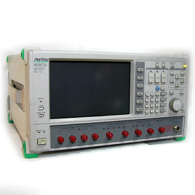
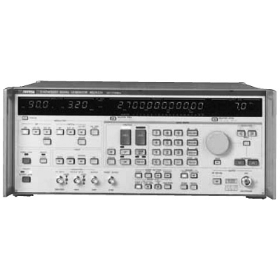
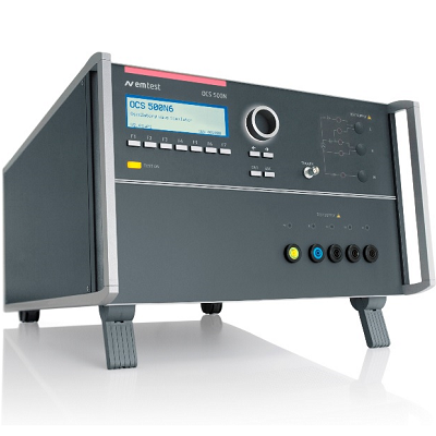
Anritsu MG3671B Digital Mod. Signal Generator 300 kHz - 2.25/2.7GHz
Description
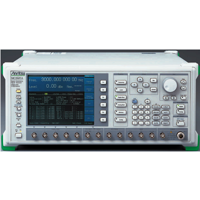
The MG3670B/C, MG3671A/B is a digital modulation signal generator equipped with a high performance quadrature modulator. It out- puts the signals needed to develop, test and evaluate digital mobile communications equipment and related devices with expansion units.The MG3670B/C, MG3671A/B covers the frequency range from 300 kHz to 2.25 GHz (MG3670B/C)/300 kHz to 2.75 GHz (MG3671A/B), and provides a stable and precise output as well as spectrum purity up to a maximum output of +13 dBm, even with modulation. In addition to testing receiver sensitivity and excess input, it can be used for testing IF stage performance and for evaluating device quality. A CMOS-level mode is provided for I/Q signal input. The input frequency band covers the CDMA spread spectrum band, expanding the range of applications.
The MG3670C and MG3671B are expanded applications by rear panel extension connectors to use for auxiliary signal output function special to communication system. MG3670B/C and MG3671A/B can be used in combination with up to seven modulation units, and a burst function unit, simultaneously.
The MG0301C/0302A/0305A/0307A/0311A modulation units have a continuous data generator capable of generating arbitrarily programmable data signals and ITU-T specification PN9/15 stage PRBS signals, as well as band-limiting filters, and they can output I/Q base- band signals.
The MG0303A Burst Function Unit uses the frame and slot configuration stipulated by various communication systems, and has a modulation pattern generator function and a function for ramp control of carrier burst signals. It can also handle data editing and scrambling. The MG0310A Modulation Unit generates SS + QPSK/OQPSK modulated (1.2288 Mcps) I/Q baseband signals, supporting the CDMA system (TIA/EIA/IS-95) used in US Digital Cellular Systems and the US Personal Communications Service (PCS).
Anritsu-developed DSP and ASIC technology is used in the MG0310A to achieve superior waveform quality factor () and spurious emission characteristics. Channel multiplexed signals are supported for both forward and reverse links.
With two MG0310A units mounted in the MG3670C/3671B, all the test signals required to conform to TIA/EIA/IS-95, -97 & -98 can be generated. Simultaneous outputs from the rear extension connectors using long & short codes, etc., support a wide range of applications including RF related tests, IF stage performance tests, and device and module quality evaluation. (Option 25 is required to install the MG0310A in the MG3670B/3671A. The auxiliary signal output function is not installed, so long/short codes cannot be output).
Features
- Compatible with communication system measurement signals of Japan, North America and Europe
- High modulation accuracy (<1.8% rms vector error)
- Outputs modulation signals suited to each communication systems
- Internal pattern generator with data-editing and scrambling functions
- Outputs IS-95 channel multiplex signal
Specifications
|
Carrier frequency |
Frequency range |
300 kHz to 2250 MHz (MG3670B/C), 300 kHz to 2750 MHz (MG3671A/B) |
||
|
Accuracy |
Depends on installed reference oscillator*1 |
|||
|
Internal reference oscillator |
Frequency: 10 MHz Start-up characteristics: ≤1 x 10⁻⁷/day (after 30-min. warm-up), ≤5 x 10⁻⁸/day (after 60-min. warm-up) Aging rate: ≤2 x 10⁻⁸/day (after 24-h warm-up) Temperature characteristics: ≤±5 x 10⁻⁸ (0˚ to 50˚C) |
|||
|
External reference input |
10 MHz or 13 MHz (±10 ppm), 2 to 5 Vp-p, BNC connector (rear panel) |
|||
|
Reference output |
10 MHz, 2 to 5 Vp-p, BNC connector (rear panel) |
|||
|
Output |
Level range |
–143 to +13 dBm (resolution: 0.1 dB) |
||
|
Frequency response |
≤±1 dB (at 0 dBm output) |
|||
|
Level accuracy |
Output level/frequency |
≤1000 MHz |
>1000 MHz |
|
|
–33 to +13 dBm |
±1 dB |
±2 dB |
||
|
–123 to –33.1 dBm |
±1.5 dB |
±2 dB |
||
|
–136 to –123.1 dBm |
±3 dB |
±4 dB |
||
|
Impedance |
50 Ω, N-type connector |
|||
|
Continuously variable level |
Continuously variable output over 20 dB range (+8 to –12 dB) in 0.1 dB steps within upper and lower limits of any output level |
|||
|
Level unit |
dBm, dBµ, µV, mV, V (dBµ, µV, mV, V selected terminate/open voltage display) |
|||
|
Interference radiation |
≤1 µV *Measured 25 mm from cabinet (except rear panel) with two-turn 25 mm diameter loop antenna, terminated with 50 Ω load, ≤+5 dBm output, carrier wave |
|||
|
Signal purity |
Spurious |
≤–65 dBc (≥100 kHz offset, ≤±100 MHz bandwidth), ≤–50 dBc (≥100 kHz offset, full band), ≤–40 dBc [spurious of (5.4–Fout) GHz at ≥2.65 GHz], ≤–30 dBc (harmonics) |
||
|
SSB phase noise |
≤–120 dBc/Hz (100 kHz offset, carrier wave) |
|||
|
Digital modulation |
Internal modulation |
Depends on installed modulation unit (MG0301C/0302A/0305A/0307A/0310A/0311A/0312A) |
||
|
External modulation |
Any modulation using I/Q input signal Input frequency: DC to 1.2 MHz*2 Input level: √ I2 ± Q2 ≤0.5 Vrms, BNC connector *I/Q ≤1.5 Vp-p (50 Ω), I/Q ≤10% to 100% of 1.5 Vp-p (CMOS) Vector error: ≤1.8%rms (I/Q input level: 1 Vrms/50 Ω, at ≤+5 dBm output) |
|||
|
I/Q output |
Outputs I/Q signal at internal modulation (MG0301C/0302A/0305A/0307A/0310A/0311A/0312A installed) |
|||
|
Pulse modulation |
Input |
TTL level, BNC connector, polarity selectable |
||
|
On/off ratio |
≥40 dB (at ≥0 dBm output) |
|||
|
Transition time |
≤2 µs, minimum pulse width: 10 µs |
|||
|
Memory function |
Frequency memory |
1000 carrier frequencies (save and recall) |
||
|
Parameter memory |
100 panel settings (save and recall) |
|||
|
Other functions |
Relative display |
Carrier frequency, output level |
||
|
I/Q signal adjustment |
Offset, balance, phase (only output) of I/Q input/output signal |
|||
|
Backup |
Last settings stored at power-off |
|||
|
Reverse power protection |
Maximum reverse input power: 50 W (<1000 MHz), 25 W (≥1000 MHz), ±50 V (DC) |
|||
|
GPIB |
All functions except power switch and panel lock switch controlled Interface function: SH1, AH1, T6, L4, SR1, RL1, PP0, DC1, DT0, C0, E2 |
|||
|
Operating temperature |
0˚ to 50˚C |
|||
|
Power |
100 to 120/200 to 240 Vac (switchable), 47.5 to 63 Hz, ≤550 VA |
|||
|
Dimensions and mass |
(426±5) W x (221.5±4) H x (451±5) D mm, ≤27 kg |
|||
|
EMC |
EN55011: 1991, Group 1, Class A EN50082-1: 1992 |
|||
|
Safety |
EN61010-1: 1993 (Installation Category II, Pollution Degree II) |
|||
