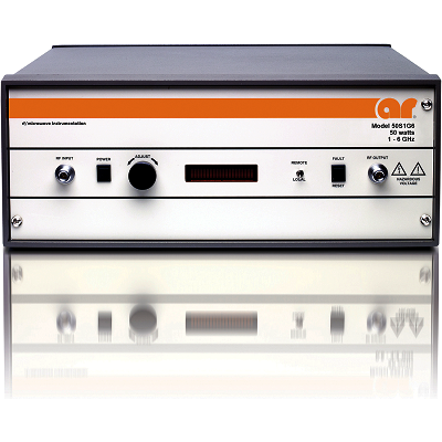
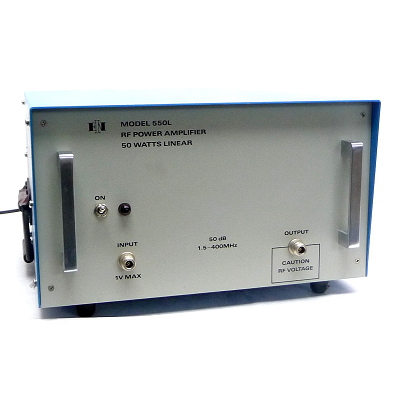
IFI T84-1000 TWT RF Microwave Power Amplifier 4 GHz – 8 GHz 1000W
Description
Instruments for Industry (IFI) T84-1000 TWT RF Microwave Power Amplifier provides outstanding RF performance. IFI “T-1000 Series” products are a mature design but incorporate the latest features with respect to control and monitoring. These amplifiers are “State of the Art”; have field proven reliability and unsurpassed performance as the best in the industry. These products are available in a wide range of frequency bands from 1 GHz – 18 GHz at 1000 watts.
Operation safety and ease of use are paramount in IFI product designs. The IFI T-1000 Series include a full complement of RF and hardware protection systems including high VSWR, over-current and voltage protection as well as redundant thermal and airflow sensors to prevent the TWT from overheating. In addition, the T-1000 series includes a state-of-the-art interface that is sophisticated, comprehensive, but yet simple to use.
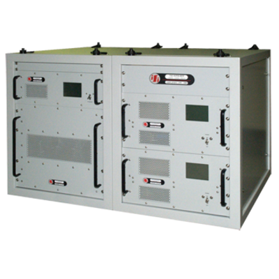
IFI amplifiers feature modular construction and this concept of modular design minimizes internally produced EMI signal leakage and provides easy access for field service and rapid turnaround at depot level repair facilities.
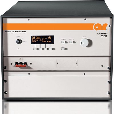
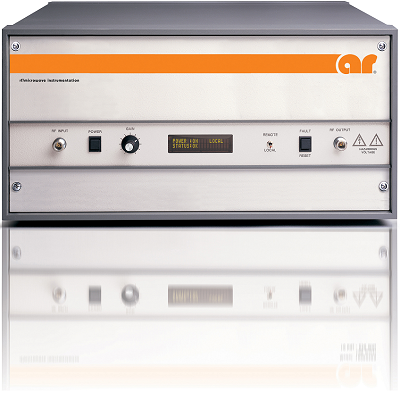
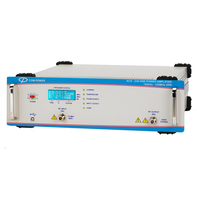
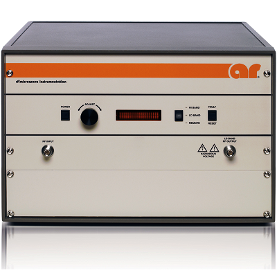
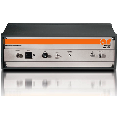
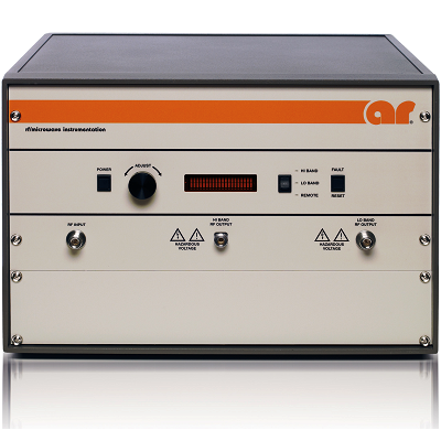
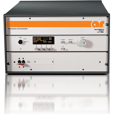
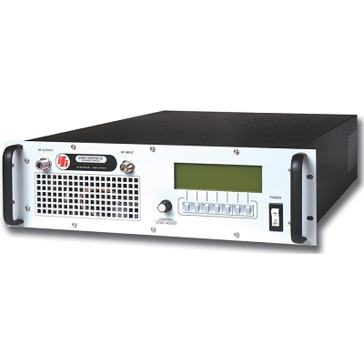
The backlit LCD screen shows forward/reverse power indication, system status and self-diagnostic information. All the amplifier operating parameters are simultaneously available in the amplifier front panel display as well as over the remote bus. Selection switches allow you to switch the amplifier to the desired mode of operation for local control if the unit is not being operated remotely.
For computer automation both an RS-232 and IEEE-488 interface are included. To meet individual application needs, the T-1000 Series amplifiers can be easily customized with harmonic filters or other options. With this capability and its reliable elegant design, the T-1000 series amplifiers are the perfect amplifier for your microwave needs.
Features
- Instantaneous Broadband Frequency range
- Modular Design Construction
- Rugged Construction & High Reliability
- Backlit LCD Display
- Integrated Force Air Cooling
- Self-diagnostic circuitry
- IEEE-488 interface, RS232
- Solid State Power Supply
Specifications
|
Input/output Impedance |
50 ohms |
|
RF Input/ Sample Connectors |
Type N Female, unless specified otherwise |
|
RF Output Connector |
Type 716 Female up to 7.5 GHz, 4 – 8 GHz is WRD350 8 – 12 GHz is WR90, 12 – 18 GHz is WR62, 7.5 – 18 GHz is WRD750, 6.5 – 18 GHz is WRD650 Other waveguides available by request or specification (see Option 117) |
|
Input VSWR |
2.0:1 |
|
Output VSWR |
2.5:1 |
|
Pulse Input |
BNC Female Front Panel {TTL into 50 ohms standard} consult factory for special requirements |
|
Pulse Width Range |
Up to CW |
|
PRF Range |
Up to 100 kHz Standard, Higher PRF ranges available consult factory |
|
Duty Cycle |
Up to CW (Higher PRF ranges subject to TWT specification) |
|
Rise & Fall Time |
25 nsec nominal; 40 nsec maximum |
|
Pulse to Pulse Jitter |
±5 nsec maximum |
|
Pulse Width Jitter (Distortion) |
±5 nsec maximum |
|
Pulse Recovery Time |
150 nsec maximum |
|
Pulse Delay |
250 nsec maximum / 180 nsec typical |
|
Pulse Droop |
0.5 dB/100 usecs, 0.1 dB/10 usec |
|
Power Output Stability |
0.2 dB Pulse to Pulse at constant drive level & PRF |
|
Pulse On/Off Ratio |
80 dB |
|
Phase Stability Pulse to Pulse |
±1 degree nominal |
|
Operating Temp |
0º to 50º C |
|
Non-operating Temp |
-40º to 70º C |
|
Humidity |
95% without condensation |
|
Altitude |
10,000 feet operating, 50,000 non-operating |
|
Cooling System |
Air cooled, self contained |
|
Modulation |
All types, AM, FM, Pulse |
|
Configuration |
Rack Mount as specified in Model Table |
|
Spurious Outputs |
<-60 dBc nominal |
|
Standard Prime Powers |
100, 115, 120 VAC ±10% 50/60 Hz, single phase |
|
Special Prime Powers other then listed are subject to availability |