Com-Power AHA-118 Active Double Ridged Horn Antenna 1 GHz - 18 GHz
Description
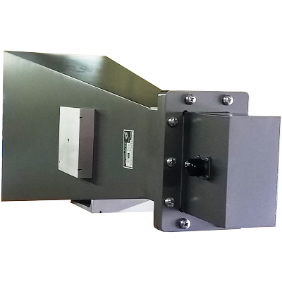
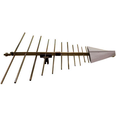
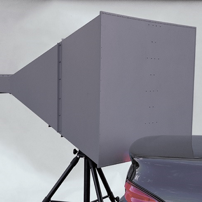
The model AHA-118 Active Horn Antenna is basically the AH-118 Horn Antenna with an integrated preamplifier. The preamplifier has a nominal gain of 20 dB for the entire frequency range. The preamplifier improves the effective system noise performance for emissions testing as explained below. The antenna AH-118 is linearly polarized and has a frequency range of 1-18 GHz.
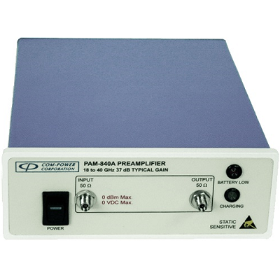
The output of the antenna is connected to the preamplifier by a short low loss cable, which can be removed. This arrangement makes it possible to (1) insert a filter before the amplifier and (2) use the antenna alone for transmission. The filter insertion capability is important and is required in presence of a high-level signal (such as fundamental frequency), which possibly could saturate the amplifier if the filter is not used. The transmitted signal flow is in opposite direction and uses a higher power level. Both conditions could damage the preamplifier if not removed.
This antenna is constructed using lightweight aluminum with a corrosion resistant conductive coating. The rear mounting plate of the AHA-118 has 1/4 inch x 20 threads. These threads allow the antenna to be mounted on a model AT-100 antenna tripod or any tripod with similar mounting arrangement. The antenna is powered by a supplied external DC wall mount adapter.
Features
- Frequency Range – 1 to 18 GHz
- Increased Sensitivity with a Built in Preamp
Com-Power AHA-118 Application
This antenna is suitable for accurately receiving low amplitude radiated emission signals. It is used during EMC testing for various standards such as FCC part 15, CISPR, and FAA for EMC emissions.
For obtaining valid data during the test, it is imperative to maintain signal level above the noise floor. In a typical setup, a receiving antenna is connected to a preamplifier that is located next the spectrum analyzer. The output of the preamplifier is then fed to the spectrum analyzer. In this arrangement, since the location of the preamplifier is far from the antenna, the interconnecting cable is long. A combination of factors such as a long cable, increasing cable loss (especially for frequencies above 1 GHz), and high antenna factors reduce the signal level to below the noise floor of the preamplifier; and that produces invalid readings. Boosting the signal at the antenna, prior to its attenuation by long cables keeps it from falling below the noise floor.
Each antenna is individually calibrated. The correction factors and certificate of calibration is shipped with the antenna. The data also includes separate antenna factors and amplifier gain.
Specifications
|
Frequency Range |
1 GHz – 18 GHz |
|
|
Built-in preamp gain |
25 dB ± 2 |
|
|
Output VSWR |
2.5 :1 |
|
|
Polarization |
Linear |
|
|
Output Impedance |
50 Ω |
|
|
Connector types |
Antenna output |
N (f) |
|
Preamplifier input |
N (f) |
|
|
Preamplifier output |
N (f) |
|
|
Power input |
18 VDC, 500 mA |
|
|
Weight |
7 lbs. (3.1 kg) |
|
|
Dimensions |
10.2″ X 9.5″ X 5.6″ (25.9 cm x 24.1 cm x 14.2 cm) |
|