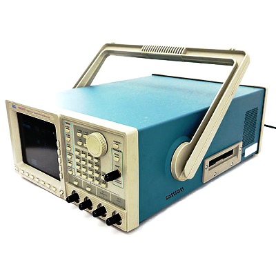
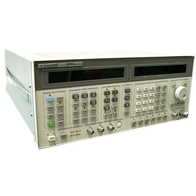
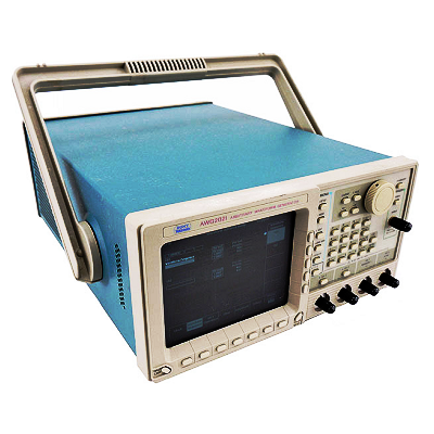
Tektronix AWG2021 Arbitrary Waveform Generator 10 Hz – 250 MHz
Description
The AWG2021 offers 250 MS/s and 256 k deep memory. As with the entire AWG2000 Series, the graphical user interface allows on-screen viewing of waveform editing, simplifying “what if” test scenarios by allowing the easy creation of composite signals.
The standard AWG2021 configuration provides one 5 V output or a second independent 5 V output (Opt. 02) each with 12-Bit vertical resolution. Frequency of channel 2 is also independently programmable. Option 03 adds a 12-Bit wide differential ECL digital port which can be used in conjunction with the marker outputs for data generation up to 14 Bits wide at up to 250 MHz. Or if you prefer, Option 04 provides TTL digital levels with up to two 12-Bit, 100 MS/s ports for a total of 28 Bits wide.
The built-in frequency domain (FFT) editor (Opt. 09) is a perfect addition for customers performing proprietary or standard modulation simulations, filter design or in physical layer testing. Real-time waveform sequencing extends the effective record length output to over a billion points!
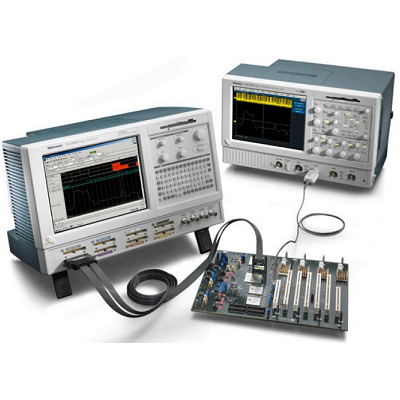
The AWG2021 easily simulates signals where moderate point definition and long records are required for simulating very complex waveform conditions. Direct waveform transfer capability makes the AWG2021 the perfect complement to selected Tektronix oscilloscopes.
Features
- 250 MS/s Clock Rate Provides up to 125 MHz Waveforms
- 256 k Memory Depth
- 12-Bit Vertical Resolution
- Direct DSO Waveform Transfers
- Region Shift Function Provides 4 ps Edge Placement
- Optional 12-Bit 250 MHz (ECL) or 12/24-Bit 100 MHz (TTL) Digital Data Generator
- Built-in 1.4 MB, 3.5 in. Floppy Disk
- FFT Frequency Domain Editor (Opt. 09)
- Real-time Waveform Sequencer to Easily Create Automatic Test Sequences and Extremely Long Patterns
- Formula Entry of Waveforms
- Channel Summing (with Opt. 02)
- Fully Programmable from Front Panel, RS-232 and GPIB (IEEE-488.2)
Tektronix AWG2021 Applications
- Analog and Digital Modulation
- Wireless Communication
- All Forms of Fading Simulation
- Navigation
- I and Q Impairment
Specifications
|
Number of Channels |
1 ch |
|
Waveforms (Sine, Square, etc.) |
Pulse, Ramp, Sine, Square, Triangle |
|
Minimum Frequency |
10 Hz |
|
Maximum Frequency Sine wave |
250 MHz |
|
Maximum Frequency Square Wave |
50 MHz |
|
Maximum Frequency Triangle Wave |
31.2 MHz |
|
Maximum Frequency Ramp |
31.2 MHz |
|
Maximum Frequency, Pulse |
31.2 MHz |
|
Maximum Noise Generator Bandwidth |
8 MHz |
|
Simultaneous Maximum Sampling Rate/Ch |
250 MSa/s |
|
Waveform Length |
256000 points |
|
Frequency Accuracy |
0.05 % |
|
Minimum Output Voltage |
.05 mV |
|
Maximum Output Voltage |
5 V |
|
Waveform Resolution |
4 digits |
|
Output Accuracy |
1 % |
|
Output Impedance |
50 Ohm |
|
Modulation |
AM,FM,PSK,FSK |
|
Sweep Modes |
Linear, Log |
|
Trigger Modes |
Auto, Burst, Continuous Gate, Step |