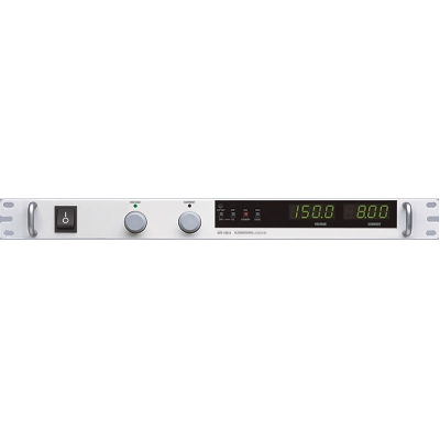
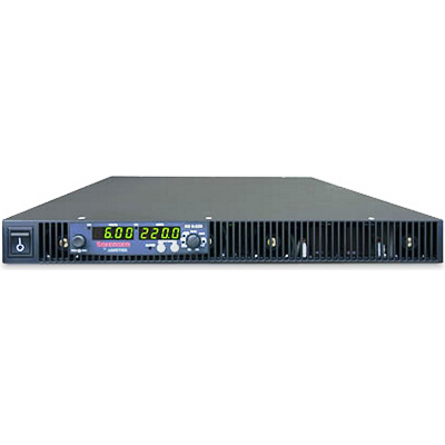
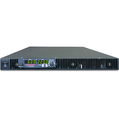
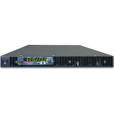
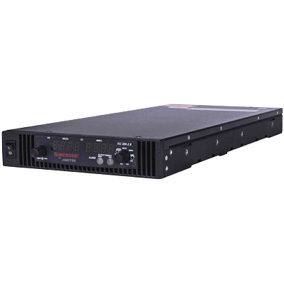
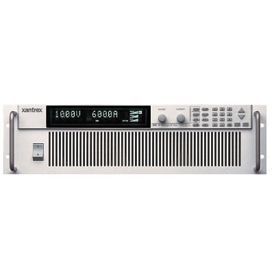
Xantrex/Sorensen XDC 100-60 Programmable DC Power Supply 100V 60A 6kW
Description
The XDC provides clean, reliable power for bench top, ATE systems, burn-in, production test and OEM applications.
The XDC has a unique embedded controller that provides menu-driven auto sequencing capability. Complex test sequences can be entered and saved via the front panel without external computers or software.
With the XDC, up to ten different test programs, each capable of 99 voltage level steps, can be constructed and executed by a manual or external trigger. Ten configurations of differing protection and output set points can also be conveniently stored, recalled or set for default at start up.
The XDC 6 kW comes in a compact 5.25-inch high rack package (3U) and is available in ten models. The XDC 12 kW comes in a 10.5-inch high rack package (6U) and is also available in ten models.
Features
- Embedded controller for menu driven auto sequencing
- Zero voltage soft switching
- Power factor correction
- Constant power mode
- Current sharing for parallel operation
- LabVIEW and LabWindows drivers
- CE, CSA, UL approvals
Specifications
| Model | XDC 10-600 |
XDC 20-300 |
XDC 30-200 |
XDC 40-150 |
XDC 60-100 |
XDC 80-75 |
XDC 100-60 |
XDC 150-40 |
XDC 300-20 |
XDC 600-10 |
| Output Voltage | 0-10V | 0-20V | 0-30V | 0-40V | 0-60V | 0-80V | 0-100V | 0-150V | 0-300V | 0-600V |
| Output Current | 0-600A | 0-300A | 0-400A | 0-150A | 0-100A | 0-75A | 0-60A | 0-40A | 0-20A | 0-10A |
| Output Power | All Models – 6,000 Watts | |||||||||
| Output Noise & Ripple: (Measurement BW: p-p is 10 Hz-20 MHz, rms is 10 Hz-100 kHz.) | ||||||||||
| Voltage rms | 10mV | 10mV | 12mV | 15mV | 15mV | 15mV | 20mV | 20mV | 30mV | 80mV |
| Voltage p-p | 75mV | 75mV | 75mV | 75mV | 100mV | 100mV | 100mV | 150mV | 250mV | 350mV |
| Current rms | 3100mA | 1600mA | 1000mA | 750mA | 450mA | 320mA | 230mA | 120mA | 50mA | 25mA |
| Output Ratings: (minimum voltage is <0.15% of rated voltage at zero output setting, minimum current is <0.2% of rated current at zero output setting with rated load resistance.) | ||||||||||
| Efficiency: (typ. at 208V input, full load)) | 85% | 87% | 87% | 87% | 89% | 89% | 90% | 90% | 91% | 91% |
| Model | XDC 10-1200 |
XDC 20-600 |
XDC 30-400 |
XDC 40-300 |
XDC 60-200 |
XDC 80-150 |
XDC 100-120 |
XDC 150-80 |
XDC 300-40 |
XDC 600-20 |
| Output Voltage | 0-10V | 0-20V | 0-30V | 0-40V | 0-60V | 0-80V | 0-100V | 0-150V | 0-300V | 0-600V |
| Output Current | 0-1200A | 0-600A | 0-400A | 0-300A | 0-200A | 0-150A | 0-120A | 0-80A | 0-40A | 0-20A |
| Output Power | All Models – 12,000 Watts | |||||||||
| Output Noise & Ripple: (Measurement BW: p-p is 10 Hz-20 MHz, rms is 10 Hz-100 kHz.) | ||||||||||
| Voltage rms | 10mV | 10mV | 12mV | 15mV | 15mV | 15mV | 20mV | 20mV | 30mV | 80mV |
| Voltage p-p | 75mV | 75mV | 75mV | 75mV | 100mV | 100mV | 100mV | 150mV | 250mV | 350mV |
| Current rms | 6200mA | 3200mA | 2000mA | 1500mA | 900mA | 640mA | 460mA | 240mA | 100mA | 50mA |
| Output Ratings: (minimum voltage is <0.15% of rated voltage at zero output setting, minimum current is <0.2% of rated current at zero output setting with rated load resistance.) | ||||||||||
| Efficiency: (typ. at 208V input, full load)) | 85% | 87% | 87% | 87% | 89% | 89% | 90% | 90% | 91% | 91% |
| AC Line Input Specifications | |
| AC Line Input | 190-242 VAC (208 Vrms nominal), 3 phase, 47-63Hz, 3 wire + Safety Ground |
| Maximum Inrush Current | 35 Arms (6kW) 70Arms (12kW) |
| Minimum Power Factor | 0.95 (At nominal input voltage and maximum power) |
| AC Line Input Operating Current | Maximum Operating: 24A/48A (at 190 VAC input, 50°C, max. load) Typical Operating: 20A/40A (at 208 VAC input, 25°C, max. load) |
| AC Line to Chassis Leakage Current | Complies with IEC 1010-1-92, UL3101-1, CSA 22.2. |
| AC Phase to Phase Leakage Current | Complies with IEC 1010-1-92, UL3101-1, CSA 22.2. |
| Input to Output Isolation | 1350VAC |
| Output Performance Specifications ( applies to both local and remote sense configurations and to all programming sources, except where noted.) | |
| Rated Output Range | 0-100% (Voltage & Current) |
| Efficiency | 82% minimum for the product line. Specific minimum efficiency limits are model dependent. 89% typical at nominal line voltage and ambient temperature. See model table. |
| Load Regulation | Voltage: 5mV + 0.05% of Vmax Current: 20mA + 0.1 % of Imax Power:1% of Pmax |
| Line Regulation | Voltage: 0.01 % of Vmax Current: 0.01 % of Imax Power: 1% of Pmax |
| Programming Range for Voltage, Current, and Power | From 0-100% of the rated maximum output. |
| Output Disabled Voltage | 0.1 % of rated maximum output |
| OVP Programming Range | 0-103% of Vmax |
| Maximum Remote Sense Line Drop Compensation | Minimum 3.8V for each line, 5V typical |
| Switching Frequency | Nominal 35 kHz; (56-130 kHz output ripple) |
| Dynamic Output Specifications | |
| Rise Time | For a programmed 0 to 100% step in output voltage No Load 100ms Full Load 100ms |
| Fall Time | For a programmed 100% to 0% step in output voltage. No Load 2s Full Load 50ms |
| Time Delay From Power On Until Output Stable | 5 seconds maximum (Within regulation envelope) |
| Time Delay From Output Enable Until Output Stable | 2s maximum (Within regulation envelope) |
| Output Hold-Up Time – Power Off | Minimum 4ms (at full load) |
| Output Hold-Up Time – Source Interruption | Minimum 4 ms with output deviation less than 5% of maximum output voltage after source intervention. |
| Transient Response Time | Voltage Mode: 3ms for a load step change from 50% to 100% or 100% to 50%, recovers within 0.75% of the output setting. |
| Mode Crossover | CV – CC Overshoot: 1% CC – CV Overshoot: 1% |
| Typical Programming Resolution | |
| Voltage | 0.002% of Vmax (Front Panel, Remote and Analog Programming Interface) |
| Current | 0.002% of Imax (Front Panel, Remote and Analog Programming Interface) |
| Overvoltage | 0.002% of Vmax (Front Panel and Remote Interface) |
| Power | 1% of Pmax (Front Panel and Remote Interface) |
| Typical Measurement Resolution | |
| Voltage | 0.002% of Vmax (Front Panel, Remote and Analog Programming Interface) |
| Current | 0.002% of Imax (Front Panel, Remote and Analog Programming Interface) |
| Power | 1% of Pmax (Front Panel and Remote Interface) |
| Programming Accuracy | |
| Voltage Programming | Front Panel and Remote Interface: 0.1% of Vmax Analog Programming Interface: 0.2% of Vmax |
| Current Programming | (ront Panel and Remote Interface: 0.3% of Imax Analog Programming Interface: 0.3% of Imax |
| Overvoltage Programming | Front Panel and Remote Interface: 0.1% of Vmax |
| Power Programming | Front Panel and Remote Interface: 2% of Pmax |
| Readback Accuracy | |
| Voltage Readback | Front Panel and Remote Interface: 0.15% of Vmax Analog Programming Interface: 0.3% of Vmax |
| Current Readback | Front Panel and Remote Interface: 0.15% of Imax Analog Programming Interface: 0.3% of Imax |
| Power Readback | Front Panel and Remote Interface: 2% of Pmax |
| 30 Minute Drift | |
| At 25°C ±5°C, with full power load after initial turn-on | Voltage: 0.04% of Vmax Current: 0.6% of Imax Power: 2% of Pmax |
| 8 Hour Drift Temperature Stability | |
| At 20°C ±5°C after 30 minutes full load operation | Voltage: 0.02% of Vmax Current: 0.04% of Imax Power: 1 % of Pmax |
| Temperature Coefficients | |
| Voltage Programming | 0.04% of Vmax/°C (Front Panel, Remote and Analog Interface) |
| Current Programming | 0.06% of Imax/°C (Front Panel, Remote and Analog Interface) |
| Power Programming | 0.1 % of Pmax/°C (Front Panel and Remote Interface) |
| Voltage Readback | 0.04% of Vmax/°C (Front Panel, Remote and Analog Interface) |
| Current Readback | 0.06% of Imax/°C (Front Panel, Remote and Analog Interface) |
| Power Readback | 0.1 % of Pmax/°C (Front Panel and Remote Interface) |
| Analog Programming Interface | |
| Programming | 0-5 VDC: Load impedance >30 kOhms 0-l0 VDC: Load impedance >30 kOhms |
| Readback | 0-5 VDC: Load impedance <500 Ohms 0-l0 VDC: Load impedance <1 kOhms |
| Isolation | Maximum working voltage of any analog programming signal with respect to chassis potential or the supply negative output is 300 VDC. |
| User Line Interface (Includes auxiliary status lines, interlock, and external trigger lines.) | |
| Maximum Current Sink Capability | Each Output: 10 mA |
| Maximum Supply Voltage | 15VDC |
| Minimum Supply Voltage | 5VDC |
| Isolation | Maximum working voltage of any user line signal with respect to chassis potential or the supply negative output is 300 VDC. |
| Environmental Specifications | |
| Temperature Range | Operating: 0° to 50°C. Consult the factory for operation below 0°C and above 50°C. Storage: -40°C-+85°C |
| Humidity Range | 30-95% RH, Non-condensing (operating and storage) |