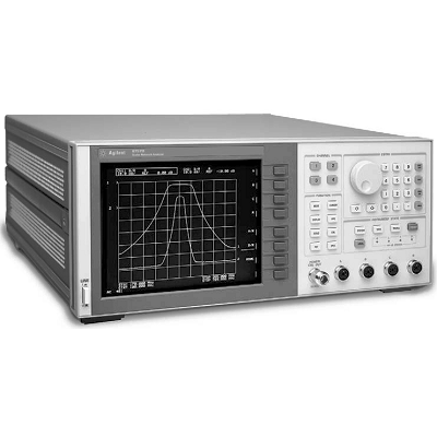
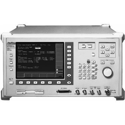
Anritsu MT8802A Radio Communication Analyzer 300 kHz - 3 GHz
Description
The MT8802A was designed to support the test needs of the manufacturing, R&D and maintenance markets. All major radio communication systems in the world, including IS-95, GSM/DCS1800/PCS1900, IS-136A, AMPS/NAMPS, PDC, and PHS, can be evaluated using just one MT8802A Radio Communication Analyzer, covering the 300 kHz to 3 GHz frequency band in one hardware platform, and the dedicated measurement software options. This tester supports Service Options 1, 2 and 9 for IS-95 and J-Std-008 as well as call processing and sensitivity testing using the loopback method for GSM/DCS1800/PCS1900 and IS-136A. The call processing function, transmission/reception measurement functions, analog measurement function, and thermocouple power meter are provided as standard features. And when the spectrum analyzer function is added as an option, the MT8802A becomes a general-purpose spectrum analyzer that covers the frequency range of 10MHz to 3GHz.
FM radio transmission/reception tests are simplified by using the analog measurement function, and the optional spectrum analyzer function covering 10 MHz to 3 GHz is very useful for maintaining and measuring spurious near carrier on production lines. GPIB and RS-232C interfaces are standard, so MT8802A can be incorporated easily into automated production lines or on-site automated testing systems.
The time required for testing equipment on production lines is greatly reduced using the high-speed adjacent channel power and occupied bandwidth measurement functions based on Anritsu's proprietary measurement algorithm and DSP (Digital Signal Processing).
Furthermore, major transmission test items such as transmission frequency, modulation accuracy (phase error), transmission power, rise/fall characteristics of burst wave, adjacent channel power, etc. can be measured.
Features
- One-Box tester for CDMA measurement
- Call processing functions
- Cellular and PCS bands
- Access probe output power measurement
- Waveform quality measurement
- Openloop power control time response measurement
- Wide-band power meter
- Frame error rate measurement
- Analog measurement functions
- Spectrum analyzer function
Specifications
|
AF Oscillator |
Frequency Range: 20 Hz to 20 kHz; Setting resolution: 0.1 Hz; Accuracy: Synchronized with reference oscillator Output level Range: 0.1 mVrms to 3 Vrms (EMF) *MAIN output: 600 ½ 0.1 mVrms to 0.3 Vrms (EMF) *MAIN output: 50 ½ Setting resolution: 1 μV (<4 mV), 10 μV (<40 mV), 100 μV (<0.4 V), 1 mV (²3 V) AF oscillator Accuracy (bandwidth: <30 kHz) Unbalanced output: ±0.5 dB (1 kHz, ³1 mV), ±1 dB (20 Hz to 20 kHz, ³1 mV) Floating output: ±2 dB (1 kHz, ³1 mV) Output impedance MAIN: 600 ½/50 ½ selectable, unbalanced, BNC Microphone: 600 ½, floating, DUT I/F Distortion: ²–50 dBc (1 kHz, 1 V), ²–45 dBc (20 Hz to 20 kHz, 1 V) *Bandwidth: <30 kHz Noise generator: White noise passed through a weighting filter (conforming to ITU-T Rec. G.227) |
|
RF Analyzer |
Power meter (narrow band) Frequency range: 10 MHz to 3 GHz Level range: 0 to +40 dBm (Main), –40 to +20 dBm (AUX) Accuracy: ±10% (Main, after calibration with internal wide band power meter) ±1 dB (AUX, 18° to 28°C, reference level: ³–12 dBm, after calibration) Linearity: ±0.3 dB (0 to –30 dB) Frequency counter Frequency: 10 MHz to 3 GHz Input level: –20 to +40 dBm (Main), –40 to +20 dBm (AUX) Resolution: 1 Hz Accuracy: ± (reference oscillator accuracy + 10 Hz) Measurement method: IF frequency counting (bandwidth: ±30 kHz) FM measurement Frequency: 10 MHz to 3 GHz Input level: –20 to +40 dBm (Main), –40 to +20 dBm (AUX) Filters HPF: 50 Hz, 300 Hz (3 dB cut-off frequency); LPF: 3 kHz, 15 kHz (3 dB cut-off frequency) Frequency deviation: 0 to 20 kHz Demodulation frequency: 30 Hz to 20 kHz Accuracy: 1% + residual FM (demodulation frequency: 1 kHz) Frequency characteristics: ±0.5 dB (referenced to demodulation frequency 1 kHz) Residual FM: 8 Hzrms (demodulation frequency: 0.3 to 3 kHz) RF analyzer Distortion: 0.3% (demodulation frequency: 1 kHz, demodulation bandwidth: 0.3 to 3 kHz, frequency deviation: 5 kHz) øM measurement Frequency range: 10 MHz to 3 GHz Input level range: –20 to +40 dBm (Main), –40 to +20 dBm (AUX) Filters HPF: 50 Hz, 300 Hz (3 dB cut-off frequency) LPF: 3 kHz, 15 kHz (3 dB cut-off frequency) Phase deviation: 0 to 10 rad Demodulation frequency: 300 Hz to 3 kHz Accuracy: 1% + residual øM (demodulation frequency: 1 kHz) Frequency characteristics: ±0.5 dB (referenced to demodulation frequency 1 kHz) Residual øM: 0.01 rad-rms (demodulation frequency: 0.3 to 3 kHz) Distortion: 0.5% (demodulation frequency: 1 kHz, demodulation bandwidth: 0.3 to 3 kHz, frequency deviation: 5 rad) FM demodulation output Frequency deviation: 0 to 40 kHz (4/40 kHz range) Demodulation frequency: 50 Hz to 10 kHz Output level: 4 Vpeak (EMF, at full-scale) Output impedance: 600 ½ Frequency characteristics: ±1 dB (referenced to demodulation frequency 1 kHz) |
|
Distortion: 1% (demodulation frequency: 1 kHz, demodulation bandwidth: 0.3 to 3 kHz, frequency deviation: 4 kHz, 4 kHz range) Filters HPF: 300 Hz (3 dB cut-off frequency), LPF: 3 kHz (3 dB cut-off frequency) De-emphasis: 750 μs |
|
|
Audio Analyzer |
Input impedance: 600 ½/100 k½ selectable, unbalanced, BNC Bandpass filter HPF: 400 Hz (for tone rejection), De-emphasis: 750 μs Weighting filter: ITU-T P.53/C-MESSAGE selectable Audio analyzer AF level measurement Frequency: 30 Hz to 20 kHz; Level: 1 mVrms to 30 Vrms; Accuracy: ±0.5 dB Distortion measurement Frequency: 100 Hz to 5 kHz; Level: 30 mVrms to 30 Vrms; Accuracy: ±1 dB (frequency: 1 kHz, distortion: 1%) AF frequency measurement Frequency: 30 Hz to 20 kHz; Level: 30 mVrms to 30 Vrms; Accuracy: ±0.1 Hz |
|
Other |
Display Color TFT-LCD, Size : 7.8 inches; Number of dots : 640 x 480 dots Hard copy: Enable data hard copy of the display through a parallel interface (applicable for ESC/P) GPIB: This equipment is specified as a device, can be controlled from external controller. Not available controller function (excluding power switch and FD ejection) Interface function: SH1, AH1, T6, L4, SR1, RL1, PP0, DC1, DT1, C0, E2 Parallel interface Others Conforms to the Centronics, outputs printing data to printer Data line exclusive for output: 8 Control line: 4 (BUSY, DTSB, ERROR, PE) Connector: D-sub 25 pins, female RS-232C: All functions controlled by external controller (excluding power switch and FD ejection) Baud rate: 1200, 2400, 4800, 9600 bps Dimensions and mass: 426 (W) x 221.5 (H) x 451 (D) mm, ²27 kg Power: 100 to 120/200 to 240 Vac (automatic voltage switch system), 47.5 to 63 Hz, ²300 VA Operating temperature: 0° to +50°C |