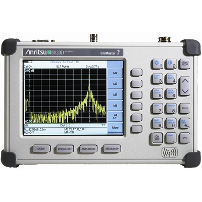
Anritsu S820D Transmission Line & Ant. Analyzer 2.0 MHz - 20.0 GHz
Description
Site Master S810D covering 2 MHz to 10.5 GHz, and S820D covering 2 MHz – 20.0 GHz, are the most accurate, reliable and convenient microwave transmission line and antenna analyzers available for installation, verification, troubleshooting, and repair of microwave communication systems. The S810D and S820D are ideal “anytime, anywhere” solutions designed for the rugged challenges faced by field technicians working with wireless and defense communications systems.
Standard measurement capabilities include VSWR, return loss, cable loss, and distance-to-fault (DTF) analysis using industry-leading frequency domain Reflectometer (FDR) technology. Patented RF interference rejection enables accurate measurements in the presence of high RF activity. Both coaxial and waveguide connections are supported. Line Sweep Tools (LST) is a free data analysis software utility that enables assessment of system trends, problems, and performance in addition to professional report generation.
Optional capabilities include 2 MHz frequency extension, power monitor, N(f) test port connector, 2-port cable loss, and GPS receiver. The 2 MHz frequency extension offers additional frequency coverage beyond the standard 25 MHz starting frequency. The power monitor is available to make power measurements quickly and easily. The 2-port cable loss employs an external CW source for conducting true 2-port cable loss measurements to 20 GHz. The built-in GPS receiver provides location information that is stamped on each trace and saved with archived data.
Broadband Site Master S810D and S820D utilizes 1-port vector error correction solving the most common and the most difficult accuracy problems of field test equipment operation and thus, improves system quality and reduces maintenance expenses. Difficult test specifications are easy to verify. Vector error correction and a simple, friendly user interface within the S810D and S820D further improve the quality and convenience of measurements compared to traditional scalar techniques. Vector error correction also improves the quality of Distance-To-Fault data. Not only is the reflection magnitude more accurate, the waveguide dispersion correction for fault distance (different frequencies travel at different speeds) is also more accurate and repeatable.
Features
- Frequency Coverage: 25 MHz to 20 GHz w/ optional extension down to 2 MHz
- Standard TFT daylight viewable color display
- Real-time measurement speed
- Real-time DTF calculations
- Features Frequency Domain Reflectometer (FDR) Technology – find cable and connector faults often missed by inferior Time Domain Reflectometer (TDR) solutions
- Only handheld product that supports waveguide
- True 2-port cable loss measurements for long microwave cable applications
- Power monitor offers power measurements in the field
- GPS receiver provides precise location information to overlay on measurements
- Handheld, battery-operated design
- Lightweight at only 5 lbs. (including battery)
- Superior Immunity to RF interference
- Locate long range problems with 517 data points
- Multilingual user interface; English, French, Chinese, Japanese, Spanish, German
- Saves 21 Measurement Test Set-Ups
- Saves up to 200 Measurement Traces
- Clearly defined user interface for Coaxial cable and Waveguide media
- Pop-up menus for cable list, waveguide list, and compatible flange list
- Quickly select cable/waveguide type and test parameters without setup error
- Alphanumeric Labeling of Saved Measurements
- Automatic Time and Date Stamp of Saved Data
- Rechargeable, Field Replaceable Battery
- Distance Measurement in Feet and Meters
- 6 Markers, Limit Lines, and Segmented Limit Lines
- RS232 Interface
Anritsu S820D Applications
Defense and Aerospace: Installation/Maintenance and Fault Detection
- Microwave cables in aircraft
- Microwave cables on board ships
- Microwave antennas
Wireless Microwave Backhaul: Installation/Maintenance and Fault Detection
- Point-to-point radios
- Microwave antennas
- Microwave cables
Other Facilities Using Microwave Links as a Communication Backbone
- Utility companies: gas, oil
Specifications
| Frequency Range | 25 MHz to 20 GHz | |
| Frequency Accuracy (CW mode) | =3 ppm at +25ºC | |
| Frequency Resolution | 10 kHz | |
| Output Power | <0 dBm | |
| Immunity to Interfering Signals | on-channel | +13 dBm |
| on-frequency | –10 dBm | |
| Measurement speed | Return Loss, SWR, DTF | =2 sec/sweep for 517 data points (CW ON) =4 sec/sweep for 517 data points (CW OFF) |
| Number of data points | 130, 259, 517 | |
| Return Loss | Range | 0.00 to 60.00 dB |
| Resolution | 0.01 dB | |
| VSWR | Range | 1.00 to 65.53 |
| Resolution | 0.01 | |
| Coax/Waveguide Insertion Loss | Range | 0.00 to 30.00 dB |
| Resolution | 0.01 dB | |
| Measurement Accuracy | =42 dB corrected directivity after calibration for <5 GHz =36 dB corrected directivity after calibration for <15 GHz =32 dB corrected directivity after calibration for >15 GHz |
|
| Test Port Connector | Precision K(f) or N(f) (Option 11NF) | |