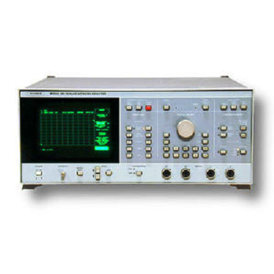
Anritsu Wiltron 561 Scalar Network Analyzer 10 MHz - 40 GHz
Description
With the addition of a sweep generator, the 561 becomes an automated transmission, return loss (SWR), and power measurement system. Operating over the 10 MHz to 40 GHz range from a single coaxial test port, the system provides fully annotated displays of test data and measurement parameters.
Under internal microprocessor control (no external control¬ler required), the 561 normalizes and simultaneously displays any two inputs on channels A, B, R1, and R2. The same inputs can be displayed as ratios A/R1, A/R2, B/R1, or B/R2. The dynamic range for each channel is 71 dB (-55 dBm to +16 dBm). Typically, the noise floor is less than 2 dBm, providing a greater than 76 dB dynamic range in almos1 all applications.
Features
- Automatic Measurements and Hard Copy Output
- Without a Controller
- Accurate Coaxial Measurements from 10 MHz to 40GHz
- Nine Stored Setups to Eliminate Set-Up Time
- Cursors, Markers, and Limit Lines to Improve Productivity
- Complete, Annotated. Step-By-Step Normalization and Measurement Procedures
- Four Measurement Channels
- Lowest Cost Network Analyzer
Specifications
|
Measurement Modes |
Measures and displays in dB swept transmission and return loss characteristics. Power is displayed in dBm. Complete measurement parameters for all modes are displayed. |
|
Frequency Range |
10 MHz to 40 GHz in coax using Wiltron 560 Series Detectors and SWR Autotesters. Measurements can be made at higher frequencies with user -supplied waveguide detectors and Wiltron 560-10BX or 560-10BX-1 Adapter Cables. |
|
Inputs |
Four inputs, A, B, R1 and R2 accept detected outputs from Wiltron 560 Series Detectors and SWR Autotesters. |
|
Dynamic Range |
71 dB (-55 dBm to +16 dBm) on all channels. Usable to -60 dBm. Noise floor is typically less than –62 dBm. |
|
Data Correction |
System residuals, including the average of open and short reflections, are stored during normalization for automatic subtraction from test data. |
|
Normalization |
During the normalization sequence 2001 points for each trace are stored with 0.002 dB resolution over any user-selected frequency range. Normalization data are automatically interpolated for ranges less than the original normalized range. |
|
Save/Recall |
Nine sets of front -panel settings can be stored tor later recall. All stored data can be previewed on the CRT or printer output prior to selection. Four of the setups include their own calibration data. |