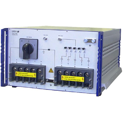
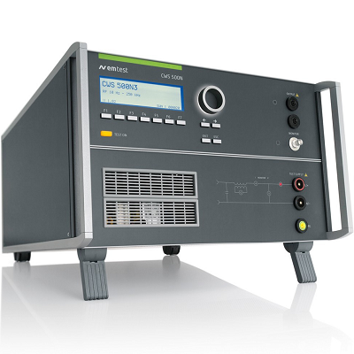
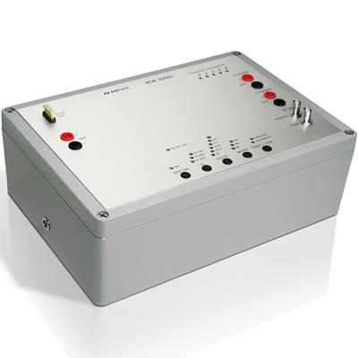
EM TEST CWS 500N1 Continuous Wave Simulator
Description
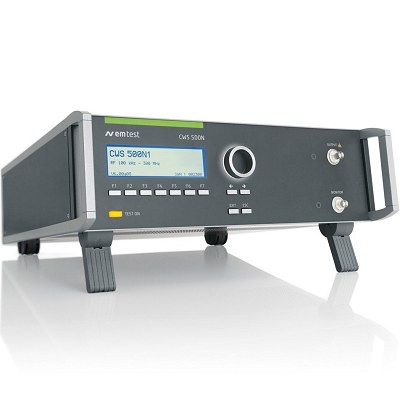
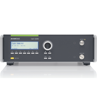
CWS 500N1 Simulator for RF Conducted Immunity Testing
EM TEST CWS 500N1 Continuous Wave Simulator is for testing conducted RF immunity as per IEC 61000-4-6 and related standards with a frequency range of 100kHz to 300MHz.
The CWS 500N1 also generates a 2 Hz 80% AM signal to test medical appliances and a 1 Hz PM signal with 50% duty cycle required to test safety equipment like fire alarms. Equipped with a 1 GHz current monitor the CWS 500N1 can be used up to 1 GHz by means of an external amplifier.
MODEL OVERVIEW
CWS 500N1.3 Simulator for RF Conducted Immunity Testing 10 kHz – 400 MHz
CWS 500N1.4 Simulator for RF Conducted Immunity Testing 100 kHz – 300 MHz
Features
- Signal generator 9kHz to 1GHz
- Amplitude modulation: 1Hz to 3 kHz (0% to 95%)
- Pulse modulation: 1 Hz – 1 kHz (10% to 90%)
- Built-in amplifier, 100kHz to 300MHz
- Built-in current monitor, 9 kHz to 1 GHz
- Automatic calibration via built-in power meter
- Connection for external amplifiers up to 1 GHz
- USB-Interface
 01
01 02
02Specifications
| TEST LEVEL | |
| Output level | 1V – max. 30V (emf) all standard test levels are guaranteed with all coupling methods |
| Output power | 80W (nominal) |
| Output impedance | Output impedance 50ohm |
| Harmonic distortion | < -20dBc at Max. Power |
| TEST FREQUENCIES | |
| Sinus (CW) | 100kHz to 300MHz |
| Frequency bands | 100kHz to 9.999MHz
10MHz to 99.99MHz 100MHz to 300MHz in the Quick Start menu the step size can be selected by the operator |
| Un-modulated signal | CW (continuous wave) |
| Amplitude modulation | 1kHz, 80%AM as per IEC 61000-4-6
2Hz, 80%AM as per IEC 60601-1-2 400Hz, 80%AM |
| Pulse modulation | 1Hz, 50% duty cycle as per EN 50130-4 |
| MEASUREMENTS | |
| Monitor | Integrated RF power meter, measuring input for CDN and clamp calibration as well as current monitor for clamp applications |
| RF indicator | LED indicating the RF output status |
| LCD | Online display of the test level and the preselected frequency value |
| Cal data F1 – F5 | 5 internal memories to save calibration data, 1% step width as required by the standard |
| INTERFACE | |
| Serial interface | USB |
| Parallel interface | IEEE 488, addresses 1 to 30 |
| Fail 1 | BNC input; test will be stopped when active low |
| Fail 2 | BNC input; test status will be saved (max. 10 events) when active low. Test will continue. |
| GENERAL DATA | |
| Dimensions | 19″/3HU |
| Weight | approx. 17kg |
| Supply voltage | 115V to 230V +10/-15%, 50/60Hz |
| Input power | Max. 380W |
| Power factor | cos (phi) = 0.98 at max. output power as per IEC 555 |
| Fuses | 2 x 6.3AT (115V) or
2 x 3.15AT (230V) |
| Cooling | Active cooling, air ventilation |
| Temperature | 10°C to 40°C |
| Rel. humidity | Max. 85%, non condensing |