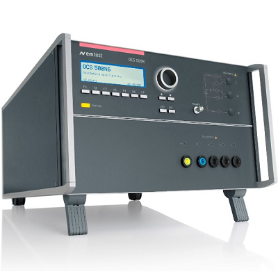
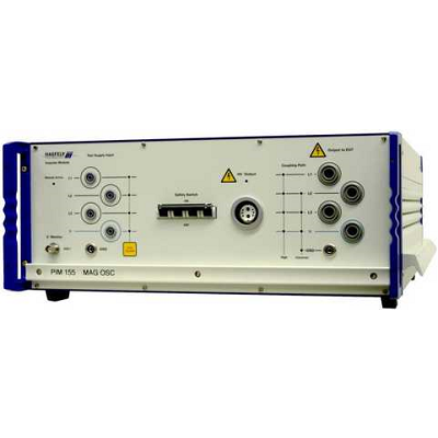
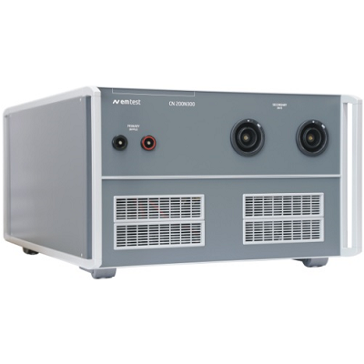
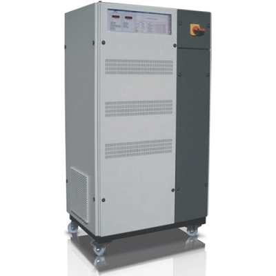
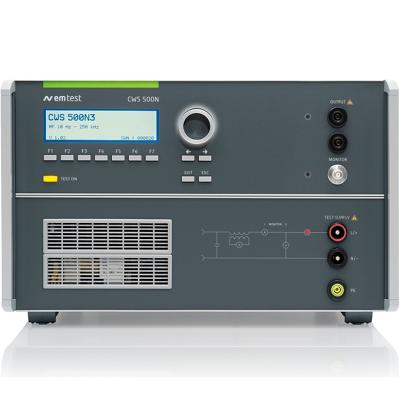
EM TEST CWS 500N3 Continuous Wave Simulator
Description
CWS 500N3 Simulator for Low Frequencies 10 Hz – 250 kHz
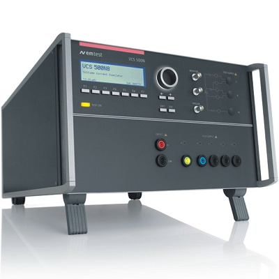
EM TEST CWS 500N3 Continuous Wave Simulator a compact single-box solution design to test the immunity to conducted low-frequency disturbances and low-frequency magnetic fields.
The CWS 500N3 includes a LF signal generator and amplifier, a low-frequency transformer 2:1, a frequency- selective voltage/current meter and load resistors as required by the standards. Various international standards and MIL requirements call for magnetic field tests in the low frequency range, the automotive industry requires conducted immunity tests with superposed sinusoidal signals on the DC supply voltage, both applications can be met by the CWS 500N3.
The CWS 500N3 meets requirements of SAE J1113-2, ISO 11452-8, RTCA/DO 160 Section 18 and MIL-STD-461 CS101, CS109 and RS101.
MODEL OVERVIEW
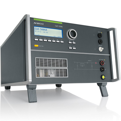
CWS 500N4 Simulator for Conducted, Common-Mode Disturbances, as per IEC 61000-4-16, IEC 61000-4-19 Annex C, DC to 165 kHz
Features
- Most compact equipment for ripple noise on ac/dc supplies and magnetic fields
- Built-in LF signal generator
- Built-in LF amplifier
- Built-in LF transformer 2:1
- Built-in frequency-selective voltage and current meter
- Built-in load resistors
- Automatic self-calibration
 01
01 02
02Specifications
| GENERAL OUTPUT CHARACTERISTICS (AMPLIFIER) | |
| Frequency range | 10Hz – 250kHz |
| Signal power | 100W (nominal) |
| Signal level | 0.001V – max. 7Vrms (14Vrms) |
| Signal current | Max. 15A rms |
| Harmonic distortion | > -20dBc at 100W power 0.5ohm |
| Current protection | Short circuit protected for current > 15A rms |
| Overvoltage protection | For voltages > 60V fed back by DUT |
| LF indicator | LED indicating the LF output status |
| LCD | Display of the test voltage and frequency |
| MEASUREMENTS | |
| General | Frequency selective instrument for
Voltage Current and Magnetic field |
| Frequency | 10Hz – 250kHz |
| Accuracy | Better than 5% |
| Current | Sense by 0.02ohm shunt.
1mA – 16A rms |
| Voltage | 0.5mV – 12 V rms |
| Magnetic field | 50ohm input for loop sensor |
| COUPLING TO BATTERY SUPPLY LINES | |
| Transformer | Impedance ratio 1:4 |
| Frequency range | 10Hz – 250kHz |
| DUT load | 60VDC up to 30A |
| DUT load | 300VAC up to 20A |
| Coupling capacitor | 100uF/10uF to shunt the DC source |
| Output impedance | less than 0.5ohm at f<80kHz |
| INTERFACE | |
| Serial interface | USB |
| Parallel interface | IEEE 488, addresses 1 – 30 |
| Fail 1 | BNC input; test will be stopped
(active low) |
| Fail 2 | BNC input; test status will be saved (max. 10 events) when active low.
Test continues |
| GENERAL DATA | |
| Dimensions | 19″/6HU (555mm x 448mm x 286mm) |
| Weight | Approx. 36kg |
| Supply voltage | 115V to 230V +10/-15%, 50/60Hz |
| Input power | Max. 600W |
| Power factor | cos (phi) = 0.96 at max. output power as per IEC 555 |
| Fuses | 2 x 6.3AT (115V) or 2 x 3.15AT (230V) |
| Cooling | Active cooling, air ventilation |
| Temperature | 10°C to 40°C |
| Rel. humidity | Max. 85%, non condensing |
- MIL-STD
- RTCA DO-160 Section 18
- MIL-STD 461
- MIL-STD 461 CS101
- MIL-STD 461 CS109
- MIL-STD 461 RS101
- RTCA DO-160
- Automotive Standards
- ISO 11452-10
- ISO 11452-8
- SAE J1113-2
- Automotive OEM Specifications
- Chrysler CS-11979
- DaimlerChrysler DC-10614
- DaimlerChrysler DC-10615
- Jaguar EMC-CS-2010JLR v1.2
- Fiat 7.Z0450 (2004)
- Ford EMC-CS-2009.1
- Ford FMC1278
- GMW3097
- PSA B21 7110
- Renault 36.00.808
- Tata TST/TS/WI/257
- Volvo STD 515-0003
- Volkswagen VW TL 825 66