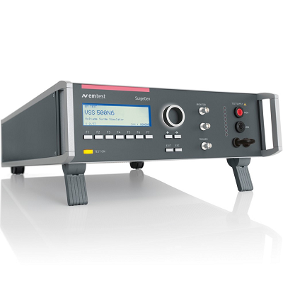
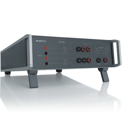
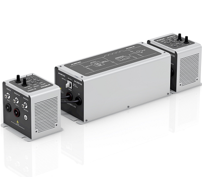
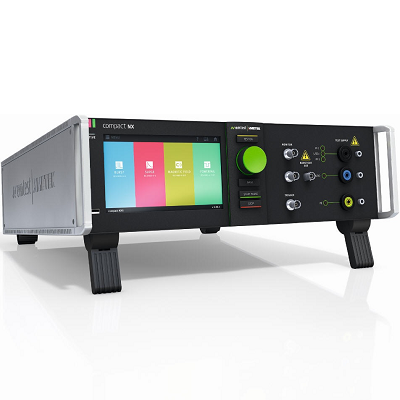
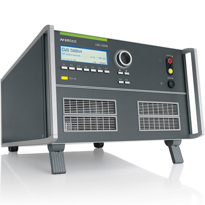
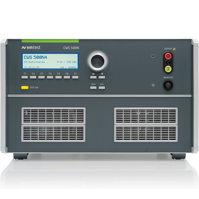
EM TEST CWS 500N4 Continuous Wave Simulator
Description
CWS 500N4 Simulator for Conducted, Common-Mode Disturbances, as per IEC 61000-4-16, IEC 61000-4-19 Annex C, DC to 165 kHz
EM TEST CWS 500N4 Continuous Wave Simulator is designed to test for immunity to conducted, common mode disturbances in the frequency range 0 Hz (DC) to 165 kHz. Such test requirements are specified in IEC 61000-4-16 and cover continuous mode testing as well as short term testing with DC, 16 2/3Hz, 50Hz and 60Hz with 4 test levels each plus a sweep mode from 10Hz to 165kHz.
Additionally, the CWS 500N4 can be used for testing electricity metering equipment as per prTR 50579 and Draft standard IEC 61000-4-19, Annex C.
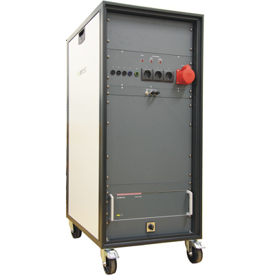
MODEL OVERVIEW
CWS 500N3 Simulator for Low Frequencies 10 Hz – 250 kHz
Features
- Most compact equipment for common-mode disturbances as per IEC 61000-4-16
- Built-in LF signal generator and LF amplifier
- Sweep mode capability 10Hz to 165kHz
- Built-in rectifier module for DC testing
- Option for Electricity Meter testing acc IEC 61000-4-19 Annex C
- Built-in voltage meter (rms values)
- Test capabilities for DC, 16 2/3Hz, 50Hz and 60Hz in continuous mode and short term mode
- USB-Interface
- Built-in semiconductor power switch
 01
01 02
02 Download Data Sheet
Print
Email
Specifications
| OUTPUT CHARACTERISTICS CONTINUOUS MODE | |
| Test frequencies | DC, 16 2/3Hz, 50Hz and 60Hz |
| Signal level | 0.1 – 35 Vrms or DC |
| Test level 1 | 1V continuous |
| Test level 2 | 3V continuous |
| Test level 3 | 10V continuous |
| Test level 4 | 30V continuous |
| Output impedance | 50ohm ± 10% |
| Total harmonics distortion | < 10% (sinusoidal waveform) |
| Ripple on DC | < 5% |
| OUTPUT CHARACTERISTICS SHORT-TERM MODE | |
| Test frequencies | DC, 16 2/3Hz, 50Hz and 60Hz |
| Signal level | 1 – 330 Vrms or DC |
| Test level 1 | 10V for 1s duration |
| Test level 2 | 30V for 1s duration |
| Test level 3 | 100V for 1s duration |
| Test level 4 | 300V for 1s duration |
| Output impedance | 50ohm ± 10% |
| Total harmonics distortion | < 10% (sinusoidal waveform) |
| Phase synchronization | 0° ± 5% |
| Ripple on DC | < 5% |
| Fall/rise time | between 1us and 5us |
| Note: | These tests require either the optional MV 2606N2.2 motor variac or the optional programmable AC voltage source ACS 500N2.3. |
| TESTING AS PER IEC/EN 61000-4-16 OUTPUT CHARACTERISTICS 15Hz – 165kHz | |
| Frequency range | 10Hz to 165kHz |
| Signal level | 0.1 to 35 Vrms |
| Test level 1 | 1V – 0.1V – 1V |
| Test level 2 | 3V – 0.3V – 3V |
| Test level 3 | 10V – 1V – 10V |
| Test level 4 | 30V – 3V – 30V |
| Output impedance | 50ohm ± 10% |
| Total harmonics distortion | < 1% (sinusoidal waveform |
| INTERFACE | |
| Serial interface | USB |
| Parallel interface | IEEE 488, addresses 1 to 30 |
| Fail 1 | BNC input; test will be stopped immediately when input becomes active low) |
| Fail 2 | BNC input; test will be stopped (when input becomes active low) and continued (input active high). After 10 fail events the test will be stopped. |
| GENERAL DATA | |
| Dimensions | 19″/6HU 555mm x 448mm x 286mm |
| Weight | Approx. 30kg |
| Supply voltage | 115V – 230V +10/-15%, 50/60Hz |
| Input power | Max. 600W |
| Fuses | 2 x 6.3AT (115V) or 2 x 3.15AT (230V)
2 x 10AT for AC-Source |
| Cooling | Active cooling, air ventilation |
| Temperature | 10°C to 40°C |