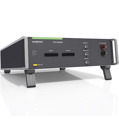
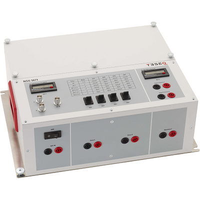
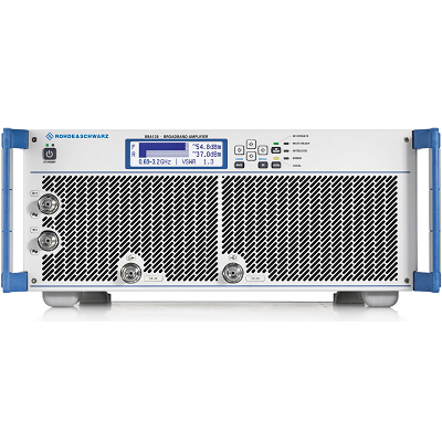
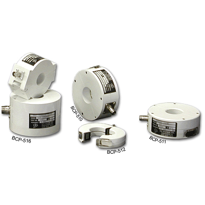
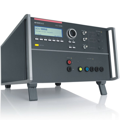
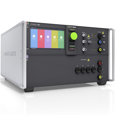
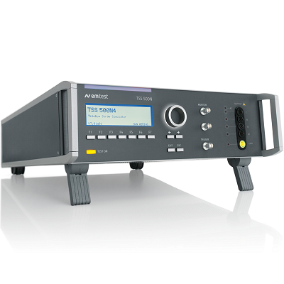
EM TEST PFM 200N100 Power Fail Simulator
Description
EM TEST PFM 200N100 Power Fail Simulators has been designed to fully meet the requirements for E10, E13 and E14 of the LV 124 and the E48-09 of the LV 148. It also allows users to perform micro-interruptions with fast rise/fall time of as low as 200ns as required by GMW 3172, sec. 9.2.18.
The PFM 200N-series includes a switch for the power supply line from 100 mA to 200A and a separate switch in the ground return path. These switches can support very high inrush currents up to several hundreds of Amperes.
MODEL SERIES OVERVIEW
PFM 200N-series Automotive Power Fail Simulator for OEM LV 124 and LV 148 and other OEM Standards
Features
- Switch for Power supply (100 A / 200 A) and signal/data lines (2 A)
- Pulses E10 and E13 of the LV 124/LV 148 standard
- Bi-directional current direction
- Separate switch in the ground line
- Rise/fall time less than 200ns
- Built in short-circuit switch <100 mohm
- Rated voltage ±100 VDC
- short-circuit-proof
Download Data Sheet
Print
Email
Specifications
| GENERAL SWITCH | |
| Switch Impedance | Power lines: < 50 mOhm
Data lines: < 500 mOhm |
| Internal switch | Short circuit switch (DC+ to DC-), impedance <100 mOhm) |
| Internal switch | 100 mOhm, per LV 124 |
| Internal switch | Low |
| Internal switch | High |
| POWER LINE SWITCH | |
| Switch | 2 Switches in the circuit
– DC+ Power line – DC- Ground line |
| DUT voltage | ± 100 VDC |
| DUT current | 100 mA to 100 A, 200 A @ 25 °C |
| Current direction | Bi-directional |
| Switching time | < 200 ns (rise/fall time) |
| Repetition rate | 10 μs – 1 h |
| Drop duration | 1 μs – 1 h |
| Peak current | 400 A for 200 ms
1,350 A for 1 ms automatic switch-off if I > 1,350 A |
| Safety | Short circuit protection |
| SWITCH FOR SIGNAL- AND DATALINE SWITCH | |
| Channels | 16 in depend switched lines |
| DUT voltage | Max. ± 40 VDC |
| DUT current | 100 μA to 2 A, per channel @ 25 °C |
| Current direction | Bi-directional |
| Switching time | < 1 μs (rise/fall time) |
| Repetition rate | 500 μs – 1 h |
| Drop duration | 1 μs – 1 h |
| Bandwidth | 50 MHz / 3 dB |
| Peak current | 5 A for 200 ms |
| Safety | Short circuit protection |
| Connector | PHOENIX, DFMC connector, 1.5 mm2, Push-in-spring cage connection |
| INTERFACE | |
| Frame bus | Control cable to AutoWave |
| Monitor Output | DUT out, differential, BNC plug on front panel
Ratio 1:20 |
| GENERAL DATA | |
| Dimensions | 19″/3 HU, 448 mm x 536 mm x 154 mm |
| Weight approx. | 10.5 kg |
| Supply voltage | 100 V – 265 VAC, 50/60 Hz |
| Fuses | 2 x 2 AT |
| Reference temperature | 23 °C ±5 °C |
| Temperature | 10 °C to 35 °C |
| Humidity | 25 % to 75 %, non-condensing |
| Atmospheric pressure | 86 kPa (860 mbar) to 106 kPa (1 060 mbar) |
- Automotive OEM Specifications
- BMW GS 95003-2
- BMW GS 95024-2-1
- BMW GS 95026
- BMW QV 65013 (2010-06)
- Chrysler CS-11979
- Chrysler PF-9326
- Cummins 14269 (982022-026)
- DaimlerChrysler DC-10615
- DaimlerChrysler DC-10842
- Fiat 9.90110
- GMW3172
- Hyundai ES 39110-00
- Iveco 16-2103
- Kia/Hyundai ES 95400-10
- Mercedes-Benz MBN 10615
- Mercedes-Benz MBN LV 124-1
- Mercedes-Benz MBN LV 148
- PSA B21 7110
- Renault 36.00.808
- Tata TST/TS/WI/257
- Toyota TSC3500G
- Toyota TSC3590G
- Toyota TSC6203G
- Toyota TSC7203G
- Volvo STD 515-0003
- Volkswagen VW 80000
- Volkswagen VW 82148
- Mercedes-Benz MBN LV 123
