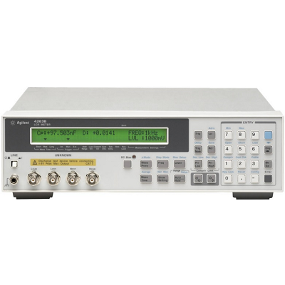
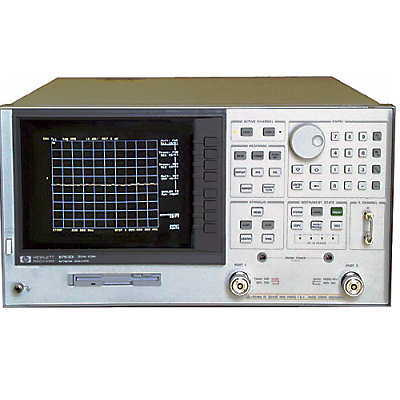
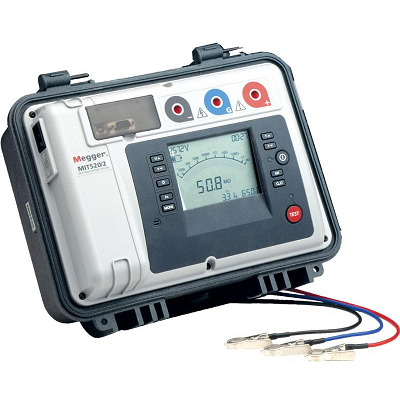
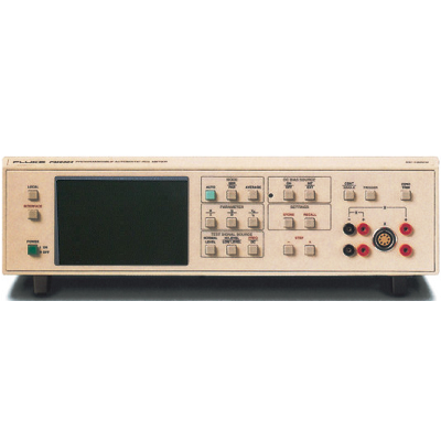
HP / Agilent 4263B LCR Meter
Description
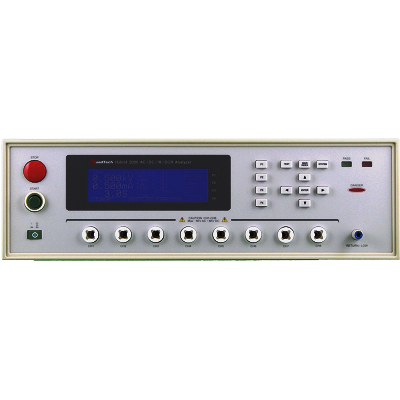
HP 4263B LCR meter is Hewlett-Packard's most cost-effective low-end LCR meter, designed for both component evaluation on the production line and fundamental impedance testing for bench-top applications. The 4263B has five test frequencies that allow you to simulate testing under the correct conditions: 100 Hz, 120 Hz, 1 kHz, 10 kHz, and 100 kHz. An optional 20 kHz test frequency can be added to those five frequencies Option 002).
High-Speed Measurements
The 4263B can boost throughput with a measurement speed of 25 ms at any test frequency. This ability improves the throughput of electrolytic capacitor and transformer testing. The 4263B can check the contact condition between the test terminals and the device-under-test (DUT). This function ensures the reliability of PASS/FAIL testing with automatic handlers in production. The quick recovery system of the 4263B improves throughput. Normal operation is resumed the instant a faulty DUT is removed from the handler, so the handler can always be operated at its full speed.
Electrolytic Capacitor Measurements
The 4263B's accuracy and wide measurement range are the right tools to make precise measurements of electrolytic capacitors. Charged capacitors can discharge through the front end and destroy an instrument. The 4263B's front end is designed for protection and maintains test integrity.
Transformer Parameter Measurements
With the 4263B's ability to make turns ratio (N), mutual inductance (M), and dc resistance (DCR) measurements, data calculations and changing test setups are no longer time-consuming tasks (Option 001). The flexible signal level setting and the voltage-and-current monitor function facilitate the use of the H4263B for level dependent DUTs, such as core inductors.
Features
- 0.1% basic accuracy
- 100 Hz, 120 Hz, 1 kHz, 10 kHz, 100 kHz test frequencies
- 20 m to 1 Vrms in 5m Vrms steps
- Test signal level monitor function
- High-speed measurement: 25 ms
- High-speed contact check
- Wide capacitance test range
- Transformer parameter measurements (optional)
Specifications
|
Measurement Functions |
||
|
Measurement Parameters |
|Z|, |Y|, q, R, X, G, B, L, C, Q, D, ESR Opt. 001: Add DCR (dc resistance), N (turns ratio), and M (mutual inductance) measurement. |
|
|
Measurement Circuit Mode |
Series and parallel |
|
|
Mathematical Functions |
Deviation and percent deviation |
|
|
Test Cable Lengths |
0 m, 1 m, 2 m, 4 m (freq. = 100/120/1k Hz); 0 m, 1 m, 2 m (freq. = 10k/20k Hz); 0 m, 1 m (freq.= 100 kHz) |
|
|
Test Signal Information |
||
|
Test Frequency |
100 Hz, 120 Hz, 1 kHz, 10 kHz, and 100 kHz Opt. 002: Add 20 kHz test frequency |
|
|
Frequency Accuracy |
± 0.01% (freq. = 100 Hz, 1 kHz, 10 kHz, (20 kHz, 100 kHz), ± 1% (freq. = 120 Hz) |
|
|
Output Impedance |
100 Ω ± 10%, 25 Ω ± 10% (± 1 Ω range) |
|
|
AC Test Signal Level |
20 m to 1 Vrms in 5m Vrms steps |
|
|
Accuracy |
± (10% + 10 mV) |
|
|
Internal dc Bias |
Level: 1.5 and 2 V Accuracy: ± (5% + 2 mV) |
|
|
External dc Bias |
0 to +2.5 V |
|
|
Measurement Range |
Parameter |
Measurement Range |
|
|Z|, R, X |
1 mΩ to 100 MΩ |
|
|
|Y|, G, B |
10 nS to 1000 S |
|
|
C |
1 pF to 1 F |
|
|
L |
10 nH to 100 kH |
|
|
D |
0.0001 to 9.9999 |
|
|
Q |
0.1 to 9999.9 |
|
|
q |
-180° to +180° |
|
|
DCR |
1 mΩ to 100 MΩ |
|
|
N |
0.9 to 200 (unspecified) |
|
|
L, M |
1 µH to 100 H (unspecified) |
|
|
D% |
-999.99% to +999.99% |
|
|
Measurement Accuracy |
± 0.1% (basic) (for |Z|, R, X, |Y|, G, B, C, L) |
|
|
Measurement Time |
Mode |
Time (typical) |
|
Short |
25 ms |
|
|
Medium |
65 ms |
|
|
Long |
500 ms |
|
|
Test Signal Level Monitor |
Voltage and current |
|
|
Front-End Protection |
Internal circuit protection when a charged capacitor is connected to the input terminals. The maximum capacitor voltage is: Vmax = ±/font> (8/C) typical @ Vmax ± 250 V; Vmax = ± (2/C) typical @ Vmax ± 1000 V, C is in Farads. |
|
|
Display Digits |
3, 4, or 5 (selectable) |
|
|
Correction Function |
||
|
Zero OPEN/SHORT |
Eliminates measurement errors due to stray parasitic impedances in the test fixtures. |
|
|
Load |
Improves measurement accuracy by using a calibrated device as a reference. |
|
|
Comparator Function |
HIGH/IN/LOW for each primary measurement parameter and secondary measurement parameter. |
|
|
Contact Check Function |
Contact failure between the test fixture and device can be detected. Additional time for contact check: 5 ms. |
|
|
Other Functions |
||
|
Save/Recall |
Ten instrument setups can be saved/recalled from the internal nonvolatile memory. |
|
|
Continuous Memory Capability |
If the instrument is turned off, or if a power failure occurs, instrument settings (except dc bias on/off) are automatically memorized (± 72 hours at 23° ± 5° C). |
|
|
HP-IB Interface |
All control settings, measured values, and comparator information. |
|
|
Handler Interface |
All output signals are negative-logic, optically isolated open collectors. Output signals include HIGH/IN/LOW, no contact, index, end of measurement, and alarm. Input signals include keylock and external trigger. |
|
|
GENERAL SPECIFICATIONS |
||
|
Power Requirements |
90 to 132 V or 198 to 264 V, 47 to 66 Hz, 45 VA max. |
|
|
Operating Temperature |
0 to 45°C |
|
|
Size |
320 mm W X 100 mm H X 300 mm D (12.6 in X 3.94 in X 11.81 in) |
|
|
Weight |
4.5 kg (9.9 lb) |
|
|
Key Literature |
HP 4263B LCR Meter Product Overview, p/n 5964-6181E LCR Meters, Impedance Analyzers and Test Fixtures Selection Guide, p/n 5952-1430 |
|
