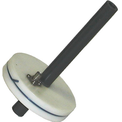
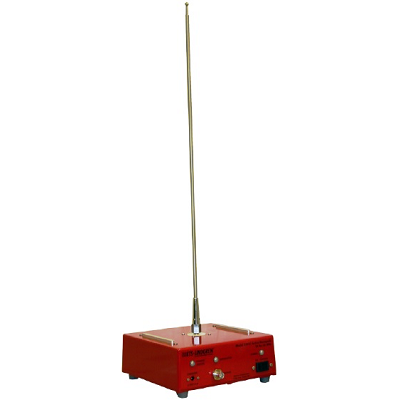
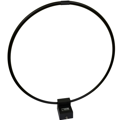
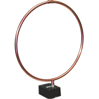
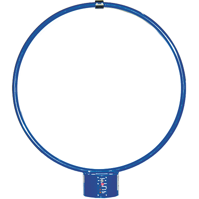
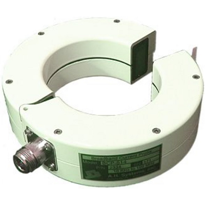
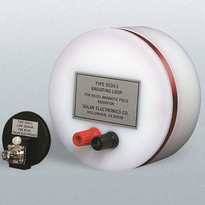
Solar 9230-1 Radiating Loop TYPE 9229-1 Loop Sensor
Description
For MIL-STD-461D/RS101 Magnetic Field Tests.
Test Method RS101 of MIL-STD-461D requires radiated magnetic fields over the frequency range 30 Hz to 100 KHz to determine the susceptibility or immunity of the equipment under test (EUT). Two loop antennas are required for compliance with the requirements. The radiating loop is 12 cm in diameter and the sensing loop (used for calibration) is 4 cm in diameter. The Type 9230-1 Radiating Loop has been designed so that the Type 9229-1 Loop Sensor can be attached at the required 5 cm distance.
Features
Solar 9230-1 TYPE 9229-1 Application
The test method requires calibration of the radiated energy at 1.0 KHz prior to the test. Calibration of the Type 9230-1 Radiating Loop is accomplished by coupling the Type 9229-1 Loop Sensor to it at a distance of 5 cm. The current level to produce 110dB/pT at 1.0 KHz is 3.0 mA. An accurately calibrated EMI meter or spectrum analyzer will measure this as 42dB/μV. Adding the correction factor of 68B/pT/μV from Fig. 2 equals 110dB/pT as required by the specification.
In those instances where the spectrum analyzer does not have sufficient sensitivity, the calibration can be accomplished just as well at a higher current level. For example, using 300 mA, the measurement would be 82 dB. Subtracting 40 dB from this answer and adding the 68 dB factor will equal 110dB/pT/μV.
Another approach to the calibration and the measurement depends on the accuracy of the EMI receiver. Simply subtract the sensor correction factor in dB/pT/μV (Fig. 2) from the desired magnetic field level in dB/pT (Fig. 3). Then adjust the current until the EMI meter reads this value in dB above one microvolt.
Example: For a field of 110dB/pT at 1.0 KHz, subtract 68 dB (Fig. 2) from this to obtain 42 dB. This value in dB above one microvolt on the EMI meter is equal to 126 μV as indicated in RS101.
A typical calibration test setup is shown in Fig. 4a. For current levels below 25 mA, it is feasible to use a standard laboratory signal generator. For higher current levels, the signal must be amplified (Fig. 4b). Both methods show a 0.1 ohm precision resistor (Type 9817-0.1) and a digital voltmeter for measuring the current.
Specifications