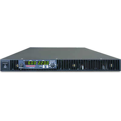
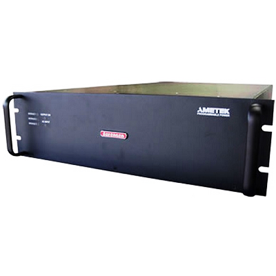
Sorensen ASD 40-750 Precision High Power DC Power Supply 40V 750A 30kW
Description
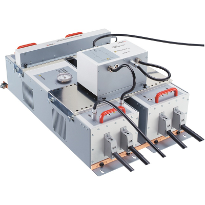
Sorensen ASD 40-750 Precision High Power DC Power Supply 40V 750A 30kW represents the next generation of precision programmable AC-DC power conversion.
The ASD with its 3U, 30kW water-cooled packaging provides the highest power density available.
The ASD is designed for industry leading load transient response with outstanding output ripple and noise. The water-cooling packaging allows for use in environments that normally exclude air-cooled power supplies.
The ASD advanced digital architecture, with real-time digital control and Graphical User Interface (GUI), enables many features to better control and monitor your process or application. The optional advanced features package includes a built-in oscilloscope function for measurement and display of: power, voltage, current, output impedance, output cable impedance and output cable voltage drop.
The ASD allows you to program different “fault levels”, enabling detection of output cabling, connections or load problems before they cause critical system problems.
The ASD can replace your PLC device by closing the loop on an external parameter such as temperature.
The ASD’s Advanced Diagnostics And Maintenance (ADAMsm) feature includes a flight data recorder feature that lets you access multiple recorded parameters, such as: voltage, current, power, load impedance, faults and input voltage. This allows you to easily determine “why” you had an unexpected outcome.
The advanced digital monitoring and control features combined with industry leading power density and reliability makes the Sorensen ASD the supply of choice for stringent and high value processes and applications.
Features
- Highest Power Density: 30kW in 3U
- Water-Cooled
- Full Digital Control Loops
- Stable operation over wide range of complex load impedances
- Advanced Digital Features
- “Flight data” recorder-like function
- Oscilloscope function
- Output impedance measurement
- Advanced fault detection – PLC feature: close loop on external variable such as temperature
- Precise programming of voltage and current slew rate for sensitive loads.
- Modules within one chassis can be connected to different loads and controlled independently.
- Industrial field bus interface (Modbus-TCP, Modbus-RTU, Ethernet/IP (Industrial Protocol)) enable real-time digital control.
- Built-in energy meter calculates the delivered energy throughout a process or period of time.
- Optional real time clock enables accurate time stamping of events.
- Built in power quality monitoring detects and saves input voltage anomalies which can be saved for later diagnostic analysis.
- Programmable analog interface scaling facilitates incorporating the ASD to existing systems with minimal effort.
- Load impedance measurement, including rate-of-change calculations, enable load “state of health” monitoring and implementation of system preventive maintenance algorithms
- Programmable filter bandwidth of the output voltage, current and power monitors let the user accommodate their response speed to particular needs.
- Full featured GUI (Graphical User Interface) helps to test and debug the system by communicating with the power supply in real time.
Specifications
| Input | ||||||||
| Voltage Ranges | 342VAC to 440VAC (model D). Nominal rating is 380/400VAC. 432VAC to 528VAC (model E). Nominal rating is 480VAC |
|||||||
| Frequency | Rated 47 through 63 Hz | |||||||
| Efficiency | >91% (typical), nominal line, full load. | |||||||
| Max Current, per phase, low line |
|
400/380Vac |
480Vac |
|||||
|
10kW unit (1 module) |
21Arms |
17Arms |
||||||
|
20kW unit (2 modules) |
42Arms |
33Arms |
||||||
|
30kW unit (3 modules) |
63Arms |
50Arms |
||||||
| Current Inrush | 200A Typical | |||||||
| Power Factor | >0.9 @ Full Load and at nominal line | |||||||
| Brownout Provisions | Designed to meet SEMI F47-0706, S3, S8, S14 at nominal input voltages | |||||||
| Output | ||||||||
| Voltage Output |
10kW |
20kW |
30kW |
Noise (pk-pk) *** |
Noise (RMS) *** |
|||
| 40Vdc |
250A |
500A |
750A |
150mV |
40mV |
|||
| 60Vdc |
167A |
334A |
501A |
150mV |
40mV |
|||
| (*) Measured at the load terminals, with 1uF in parallel and 6ft of low-inductance load cable with supply operating at full load and nominal input line voltage. (**) RMS noise is measured directly across the output terminal with supply operating at full load and nominal input line voltage. (***) Value is for 30kW, single voltage models. Other variations may increase value by 2x. |
||||||||
| Sense | To compensate load cables voltage drop, units can generate 2% additional voltage at full scale of output voltage. | |||||||
| Output | ||||||||
| Load Regulation (Specified at No load to Full load change, nominal AC input) | ||||||||
| Voltage | 0.1% of maximum output voltage/ current | |||||||
| Current | 0.1% of maximum output voltage/ current | |||||||
| Line Regulation (Specified at ±10% of nominal AC input, constant load) | ||||||||
| Voltage | 0.05% of maximum output voltage/ current | |||||||
| Current | 0.05% of maximum output voltage/ current | |||||||
| Transient Response | A 50% step load will recover to within 0.75% of original value within 1mSec | |||||||
| Stability | ±0.05% of set point after 8 hrs. at fixed line, load and temperature. After 30min warm-up. | |||||||
| Analog Remote Programming | ||||||||
| Voltage Accuracy | 0.5% of full scale | |||||||
| Current Accuracy | 1% of full scale | |||||||
| Power Accuracy | 1.5% of full scale | |||||||
| Voltage Monitoring | 0.5% of full scale | |||||||
| Current Monitoring | 1% of full scale | |||||||
| Power Monitoring | 1.5% of full scale | |||||||
| Programming range | 0-10Vdc, 4-20mA | |||||||
| Output | ||||||||
| Output Float | Units maybe put in series with the float limit of output terminals must be within ±150V of chassis potential | |||||||
| Parallel | Multiple units can be paralleled to form higher power systems. Chassis control loops are tied together so that resulting higher power systems have the same transient response as a 30kW system. Control commands are only required to be sent to “master” supply. Parallel supplies require a shielded CAT 5 cable (STP) and appropriate output wiring connections by the user. | |||||||
| Calibration | End user calibration is supported. All standard and digital calibration can be performed without removing covers. | |||||||
| Digital Control (Optional) | Ethernet (Modbus-TCP or Ethernet/IP), RS-485 (MODBUS-RTU) | |||||||
| Analog Control | All control signals are isolated from the outputs | |||||||
| Advanced Digital Features (Requires Optional Digital Control) | ||||||||
| Graphical User Interface | Graphical User Interface (Windows based) enables remote control and display of the supply operation including the a dvanced features listed below: | |||||||
| Oscilloscope Function (125 Hz) |
Up to two parameters; Voltage, current, output impedance, output cable impedance, output cable voltage drop, power delivered… | |||||||
| Data logging | Programmable update rate of 1 sec to 1000 sec (default 10 sec) with last 1000 points stored. Stored parameters include, output voltage/current, programmed set points, input voltage, output impedance, cable impedance, total power deliver, power meter, internal faults | |||||||
| System fault reporting | Outside of set point, output impedance (detection of cabling, connection or load problems) | |||||||
| Physical | ||||||||
| 30 kW | 20 kW | 10 kW | ||||||
| Width | 19.00in (48.3cm) | 19.00in (48.3cm) | 19.00in (48.3cm) | |||||
| Depth | 30.00″ (76.2 cm) | 30.00″ (76.2 cm) | 30.00″ (76.2 cm) | |||||
| Height | 3U-5.22″ rackmount (13.25 cm) | 3U-5.22″ rackmount (13.25 cm) | 3U-5.22″ rackmount (13.25 cm) | |||||
| Weight | ≤125 lbs (56.69 kg) | ≤125 lbs (56.69 kg) | ≤125 lbs (56.69 kg) | |||||
| Shipping Weight | Contact factory for more product & shipping weights | |||||||
| Mounting provisions | EIA rack-mount with slide provisions. Recommended rack slide: Jonathan slide, P/N 370EZ-28 | |||||||
| AC Input Connector | Phoenix Contact terminal block | |||||||
| Protective Ground | 1/4-20 stud | |||||||
| Output Connectors | bus bars with 3/8-16 inserted PEM nuts | |||||||
| Water Connections | 3/8-18 NPTF hex bulkhead | |||||||
| Ambient Temperature | 0 to 50ºC | |||||||
| Humidity | Relative humidity up to 95%, non-condensing | |||||||
| Water Cooling Specifications | ||||||||
| Flow | 1.5 gpm nominal, 1.25gpm minimum, 1.75gpm maximum. Internal condensation must be prevented by ensuring that the temperature of the coolant is sufficiently high compared with the ambient air dew point | |||||||
| Temperature | 25ºC nominal, 20ºC minimum, 30ºC maximum | |||||||
| Maximum pressure | 80 PSI | |||||||
| Pressure drop | typical 12 PSI @ 1.5gpm per chassis | |||||||
| Regulatory | ||||||||
| Certified to UL/CSA 61010 and IEC/EN 61010-1 by a NRTL, CE Compliant, LVD Categories: Installation Category II: Pollution Degree 2; Class II Equipment: for Indoor Use Only. Rack mount equipment requires proper enclosure provided in end use. EMC Directive, EN 61326:1998 | ||||||||