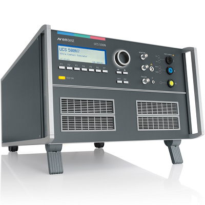
Sorensen XG 150-5.6 Programmable DC Power Supply 150V 5.6A 840W
Description
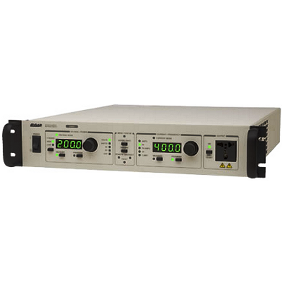
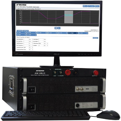
Sorensen XG 150-5.6 Programmable DC Power Supply 150V 5.6A 840W is the new standard for powerful, programmable DC power systems. Designed for test, production, laboratory, OEM and quality assurance applications, the XG provides a wealth of features to ensure accuracy and greater efficiency. It puts clean, reliable power at your disposal and delivers stable, variable output voltage and current for a broad range of development, test and system requirements.
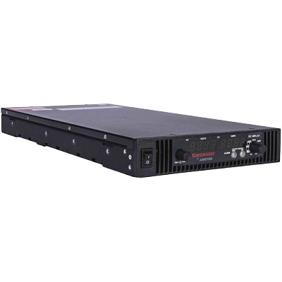
Highest Power Density
High frequency, soft switching technology in the XG Series provides up to 850 Watts in a 1U half-rack package. This represents the highest power density available from any manufacturer. With 12 models, there is a configuration available to meet every application.
Comprehensive Digital and Analog Interface Options
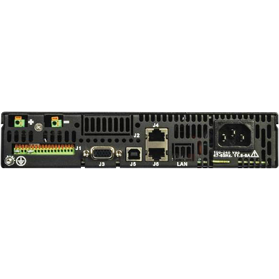
The XG comes standard with USB 2.0, RS-232, RS-485, isolated and non-isolated analog interfaces to provide a comprehensive set of options to connect to a PC or other network device. This design provides the convenience of being able to accommodate a wide range of installation configurations. Ethernet and GPIB interfaces are available as options.
Scalable, Multi-Unit Design
XG power supplies can be connected in parallel or series to produce greater current or voltage output for your applications. This scalability allows you to build rack-mounted systems with the XG that exactly meet your existing requirements, while allowing for future expansion.
Multi-Channel Support
Up to 30 XGs can be connected easily via an RS-485 bus to provide the ultimate flexibility in remote programming. This eliminates the cost and complexity of requiring GPIB cards in each unit once connected, multiple power supplies can be controlled via a single LAN, USB 2.0, GPIB, RS-232 or RS-485 interface. This provides an efficient option to centrally manage each XG needed for your applications.
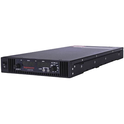
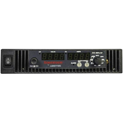
Straightforward Front Panel Controls
The XG is equipped with a unique push-button encoder and function selector dial to provide a simple, uncluttered front panel. Both voltage and current can be set quickly and easily using these two controls. Front panel access can be locked out to ensure secure remote operation. This streamlined front panel layout results in fast, intuitive set-up and operation of the XG.
Features
- Highest Power Density
- Comprehensive Digital and Analog Interface Options
- Scalable, Multi-Unit Design
- Multi-Channel Support
- Straightforward Front Panel Controls
- High Reliability
 01
01 02
02 03
03 04
04Specifications
| Output Ratings | |||||||
| Model |
Output Voltage¹ |
Output Current² |
Output Power³ |
||||
| XG 6-110 |
6 V |
110 A |
670 W |
||||
| XG 8-100 |
8 V |
100 A |
810 W |
||||
| XG 12-70 |
12 V |
70 A |
850 W |
||||
| XG 20-42 |
20 V |
42 A |
850 W |
||||
| XG 33-25 |
33 V |
25 A |
835 W |
||||
| XG 40-21 |
40 V |
21 A |
850 W |
||||
| XG 60-14 |
60 V |
14 A |
850 W |
||||
| XG 80-10.5 |
80 V |
10.5 A |
850 W |
||||
| XG 100-8.5 |
100 V |
8.5 A |
860 W |
||||
| XG 150-5.6 |
150 V |
5.6 A |
850 W |
||||
| XG 300-2.8 |
300 V |
2.8 A |
850 W |
||||
| XG 600-1.4 |
600 V |
1.4 A |
850 W |
||||
| Line Regulation | |||||||
| Model |
Voltage (0.005% of rated |
Current (0.01% of rated |
|||||
| XG 6-110 |
2.3 mV |
13 mA |
|||||
| XG 8-100 |
2.4 mV |
12 mA |
|||||
| XG 12-70 |
2.6 mV |
9 mA |
|||||
| XG 20-42 |
3.0 mV |
6.2 mA |
|||||
| XG 33-25 |
3.7 mV |
4.5 mA |
|||||
| XG 40-21 |
4 mV |
4.1 mA |
|||||
| XG 60-14 |
5 mV |
3.4 mA |
|||||
| XG 80-10.5 |
6 mV |
3.1 mA |
|||||
| XG 100-8.5 |
7 mV |
2.9 mA |
|||||
| XG 150-5.6 |
9.5 mV |
2.6 mA |
|||||
| XG 300-2.8 |
17 mV |
2.3 mA |
|||||
| XG 600-1.4 |
32 mV |
2.1 mA |
|||||
| Load Regulation | |||||||
| Model |
Voltage (0.005% of rated |
Current (0.02% of rated |
|||||
| XG 6-110 |
2.3 mV |
27 mA |
|||||
| XG 8-100 |
2.4 mV |
25 mA |
|||||
| XG 12-70 |
2.6 mV |
19 mA |
|||||
| XG 20-42 |
3.0 mV |
13.4 mA |
|||||
| XG 33-25 |
3.7 mV |
10 mA |
|||||
| XG 40-21 |
4 mV |
9.2 mA |
|||||
| XG 60-14 |
5 mV |
7.8 mA |
|||||
| XG 80-10.5 |
6 mV |
7.1 mA |
|||||
| XG 100-8.5 |
7 mV |
6.7 mA |
|||||
| XG 150-5.6 |
9.5 mV |
6.1 mA |
|||||
| XG 300-2.8 |
17 mV |
5.6 mA |
|||||
| XG 600-1.4 |
32 mV |
5.3 mA |
|||||
| Output Ratings | |||||||
| Model |
Output Noise (rms, 300 kHz) |
Output Ripple |
|||||
|
Voltage |
Current |
Voltage |
|||||
| XG 6-110 |
8 mV |
200 mA |
50 mV |
||||
| XG 8-100 |
8 mV |
180 mA |
50 mV |
||||
| XG 12-70 |
8 mV |
120 mA |
50 mV |
||||
| XG 20-42 |
8 mV |
75 mA |
50 mV |
||||
| XG 33-25 |
8 mV |
60 mA |
50 mV |
||||
| XG 40-21 |
8 mV |
45 mA |
50 mV |
||||
| XG 60-14 |
8 mV |
35 mA |
50 mV |
||||
| XG 80-10.5 |
8 mV |
25 mA |
80 mV |
||||
| XG 100-8.5 |
8 mV |
20 mA |
80 mV |
||||
| XG 150-5.6 |
10 mV |
16 mA |
100 mV |
||||
| XG 300-2.8 |
25 mV |
10 mA |
150 mV |
||||
| XG 600-1.4 |
50 mV |
6 mA |
250 mV |
||||
| 1. Maximum output voltage is guaranteed to be 0.1% of the rated voltage at zero output setting, using the front panel or digital remote programming modes. 2. Maximum output current is guaranteed to be 0.2% of the rated current at zero output setting, using the front panel or digital remote programming modes, and when measured with rated load resistance. 3. Total output power is also based on AUX1 Output Voltage (5 V) and AUX1 Output Current (0.5 A) and AUX2 Output Voltage (15 V) and AUX2 Output Current (0.5 A). 4. From 85–132 Vac or 170–265 Vac, constant load. 5. From 85–132 Vac or 170–265 Vac, constant load. 6. From no load to full load, constant input voltage. 7. For load voltage change, equal to the unit voltage rating, constant input voltage. 8. For 6 V models the current ripple is measured at 2–6 V output voltage and full output current. For all other models, the current ripple is measured at 10–100% output voltage and full output current. |
|||||||
| Output Ratings | |||||||
| Model |
Maximum Recommended Remote Sense Line Drop Compensation per Line 9 |
Up-prog. Response Time, 0~Vmax 10 |
Efficiency (100/200 VAC input) 11 |
||||
| XG 6-110 |
1 V |
60 ms |
75/77% |
||||
| XG 8-100 |
1 V |
60 ms |
77/80% |
||||
| XG 12-70 |
1 V |
60 ms |
79.5/82.5% |
||||
| XG 20-42 |
1.5 V |
60 ms |
82/85% |
||||
| XG 33-25 |
2 V |
60 ms |
83/86% |
||||
| XG 40-21 |
2 V |
60 ms |
83/87% |
||||
| XG 60-14 |
3 V |
60 ms |
83/87% |
||||
| XG 80-10.5 |
5 V |
100 ms |
83/87% |
||||
| XG 100-8.5 |
5 V |
100 ms |
83/87% |
||||
| XG 150-5.6 |
5 V |
100 ms |
83/87% |
||||
| XG 300-2.8 |
5 V |
150 ms |
83/87% |
||||
| XG 600-1.4 |
5 V |
250 ms |
83/87% |
||||
| Output Ratings | |||||||
| Model |
Down-prog. Response Time: Full Load |
Down-prog. Response Time: No Load |
Over-Voltage Trip Point |
||||
| XG 6-110 |
60 ms |
300 ms |
0.5–7.5 V |
||||
| XG 8-100 |
60 ms |
400 ms |
0.5–10 V |
||||
| XG 12-70 |
60 ms |
500 ms |
1–15 V |
||||
| XG 20-42 |
60 ms |
600 ms |
1–24 V |
||||
| XG 33-25 |
60 ms |
700 ms |
2–39 V |
||||
| XG 40-21 |
60 ms |
800 ms |
2–44 V |
||||
| XG 60-14 |
60 ms |
900 ms |
3–66 V |
||||
| XG 80-10.5 |
100 ms |
1000 ms |
3–95 V |
||||
| XG 100-8.5 |
100 ms |
1200 ms |
3–125 V |
||||
| XG 150-5.6 |
100 ms |
1800 ms |
3–180 V |
||||
| XG 300-2.8 |
150 ms |
2200 ms |
5–330 V |
||||
| XG 600-1.4 |
250 ms |
3500 ms |
5–660 V |
||||
| Output Performance Specifications | |||||||
| Temperature Coefficient | 100 PPM/° C from rated output voltage, after a 30-minute warm-up* | ||||||
| Drift (8 hours) | 0.05% of rated output voltage & current over an 8 hour interval with constant line, load & temperature, after a 30-minute warm-up | ||||||
| Hold-up Time | Typical 20 ms at any rated input line. | ||||||
| Transient Response Time 13 | Less than 1 ms for 6 V to 60 V models. Less than 2 ms for 80 V to 600 V models* | ||||||
| Meter Accuracy | 0.5% ± 1 count | ||||||
| Isolation 12 | 1500Vac or 2121Vdc between mains terminals and accessible conductive parts / chassis ground. Output to chassis 500Vac. |
||||||
| Environmental Specifications (Indoor Use) | |||||||
| Operating Temperature Range | 32°F to 122°F, 100% load (0°C to 50°C) | ||||||
| Storage Temperature Range | -4°F to 158°F (–20° C to 70°C) | ||||||
| Operating Humidity Range | 30–90% RH (no condensation) | ||||||
| Storage Humidity Range | 10–95% RH (no condensation) | ||||||
| Operating Altitude | Up to 6,500 feet (2,000 m) | ||||||
| Installation Category | II (IEC 1010-1) | ||||||
| Pollution Degree | 2 (IEC 1010-1) | ||||||
| Regulatory Approvals | |||||||
| Safety | CSA 22.2 No. 61010-1, 60950-1-07 and UL61010-1, UL60950-1-(2nd Ed) 12. Marked with cCSAus, CE for EMC & low voltage directive | ||||||
| EMC | Complies with EN61326-1 Complies with EN55022, Class B, FCC Part 15B for conducted emissions Complies with EN55022, Class A, FCC Part 15A for radiated emissions Complies with EN61000-4 series of standards for immunity |
||||||
| 9. When using remote sense, the total of the load voltage and the load line drops must not exceed the rated output of the power supply. For example, for an XG 6-110 in an application with 1 V of load line loss (0.5 V/Line), the maximum available load voltage would be 6–1= 5 V. Note: The unit may operate at higher output voltages than this, but there is no guarantee that the power supply will meet performance specifications. Ultimately, the upper limit of the output voltage will be determined by internal circuitry of the power supply (non-adjustable.) 10. With rated, resistive load. 11. At maximum output power. 12. Double insulation on primary to secondary isolation barriers. Basic insulation primary to protective earth ground. 13. Time for the output voltage to recover within 0.5% at its rated output for a load change 10-90% of rated output current. Output set point 10-100%. |
|||||||