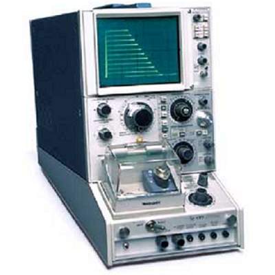
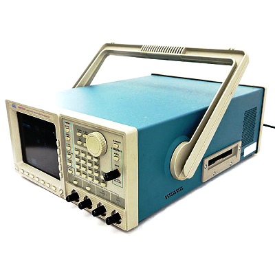
Tektronix 577 Curve Tracer – Semiconductor Testers
Description
The Tektronix 577 Curve Tracer system offers a convenient method of presenting dynamic characteristic transistor curves and a wide range of other semiconductor devices. The 577 allows dc parameter characterization of transistors, thyristors, linear ICs, diodes, SCRs, MOSFETs, optoelectronic components, solar cells, solid state displays and other semiconductor devices. Expanded parameter measurements are available for linear op-amps, SCRs and three terminal regulators when using one of three application specific adapters with the 178 Test Fixture (not-included)
The Tektronix 577 Curve Tracer provides for low current measurements with storage display capabilities and also allows characteristic curves of two devices to be overlaid. The Collector supply (five modes, five ranges) provides 6.5 V/10 A, 25 V/2.5 A, 100 V/0.6 A, 400 V/0.15 A, 1600 V/0.04 A. Current increments: 5nA/step to 0.2 A/step +/-2%. Voltage increments: 5 mV/step to 2 V/step +/-2%.
Features
Deflection Controls
- Display Mode – Norm and Dc Modes – Vertical Collector Current – Horizontal Collector Volts – Horizontal Base Volts – Step Generator Mode – Horizontal Mode
- Vertical Deflection Factor – Collector Current: 2 nA/div to 2 A/div, 28 steps (0.2 nA/div to 0.2 A/div with x10 magnification)
- Horizontal Deflection Factor:
- Collector Volts: 50 mV/div to 200 V/div (5 mV/div to 20 V/div with x10 magnification).
- Base Volts: -50 mV/div to 2 V/div (5mV/div to .2 V/div with x10 magnification)
Characteristics
- Device Lead Selection – Switch provides six different lead configurations.
- Three positions for Emitter Grounded measurements provide Step Gen, Open (or Ext), and Short base terminal connections.
- Two positions for Base Grounded measurements provide Step Gen and Open (or Ext) emitter terminal connections.
- One position provides for Emitter Base Breakdown or leakage measurements up to 25 Volts. Left-Right Switch
- Variable Voltage Supply – Continuously variable bias supply from -12 V to + 12 V.
- Storage and Nonstorage Curve Tracer System
- Test Two-Terminal and Three-Terminal Discrete Semiconductors
- Storage Capability (Model D1)
- Power Capability Up to 100 Watts
Collector Supply
- Modes/Polarity – Norm: Ac (at line frequency); positive or negative full-wave rectified ac. DC: positive or negative dc.
- Series Resistance – From 0.12 ohms to 8 M ohms in 14 steps. Peak Power Limit Setting: 100 W, 30 W, 9 W 2.3 W, 0.6 W, 0.15 W.
- Safety Interlock
Step Generator
- Current Mode – Step/Offset Amplitude Range: 5 nA/step (with x0.1 Mult) to 200 mA/step.
- Voltage Mode – Step/Offset Amplitude Range: 5 mV/step (with x0.1 Multi) to 2 V/step
- Step Rates – Selectable at x1, x2, or x4 line frequency.
- Step Family – Repetitive or single family
- Number of Steps – Selectable from 1 to 10 full-amplitude steps