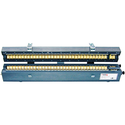
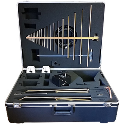
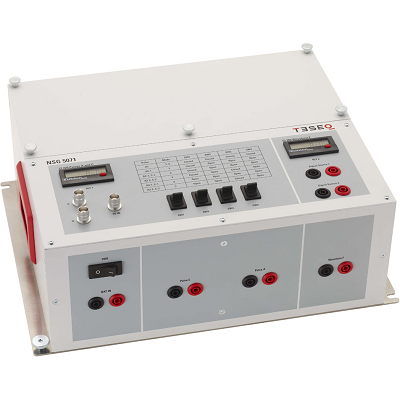
Teseq NSG 5071 Inductive Switch Transient Test Circuit
Description
Teseq NSG 5071 Inductive Switch Transient Test Circuit is designed exactly in accordance with EMC-CS-2009.1 for test CI 220 pulses A1, A2-1, A2-2, C1, C2 and RI 130 using an inductive/relay transient generator test circuit. The NSG 5071 also features the CI 260 Waveform F in this test circuit which uses the same type of relay. This test circuit is defined in annex F for the A, C pulses and RI 130 and figure 19-10 for CI 260 Waveform F.
Features
- Designed in accordance to Ford standard EMC-CS-2009
- Transients disturbances CI 220 A and C pulses
- CI 260 waveform F
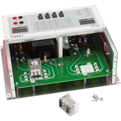
- User replaceable relays
 01
01 02
02 Download Data Sheet
Print
Email
Specifications
| Parameter | Value |
| Critical components used (as defined by the standard) |
Potter and Brumfield KUP-14A15-12 5 μH Osborn Transformer PN 8745 100 mH Osborn Transformer PN 32416 |
| DC current | 10 A with supplied relay Up to 30 A with user-installed relay |
| DC voltage | 15 V |