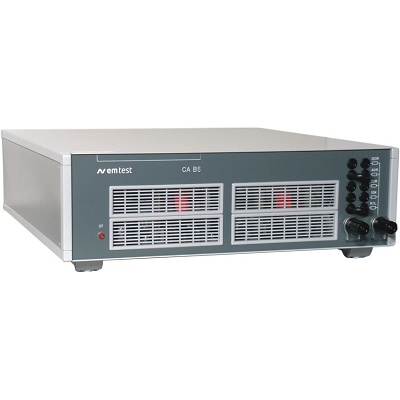
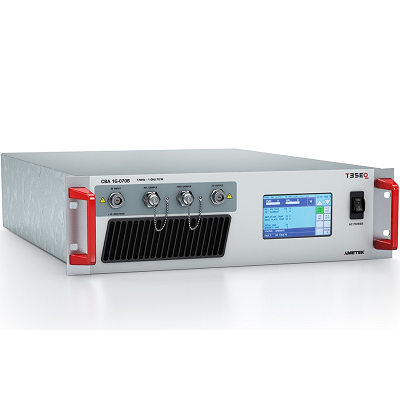
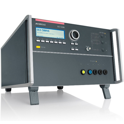
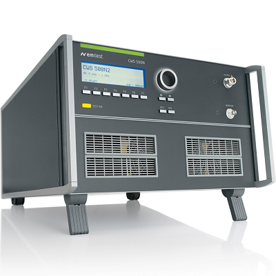
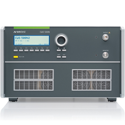
EM TEST CWS 500N2 Continuous Wave Simulator
Description
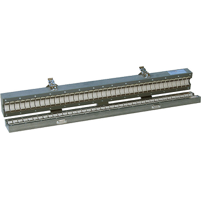
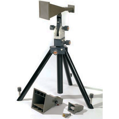
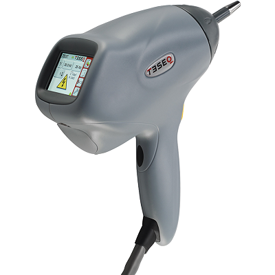
CWS 500N2 Simulator for BCI (Bulk Current Injection Testing)
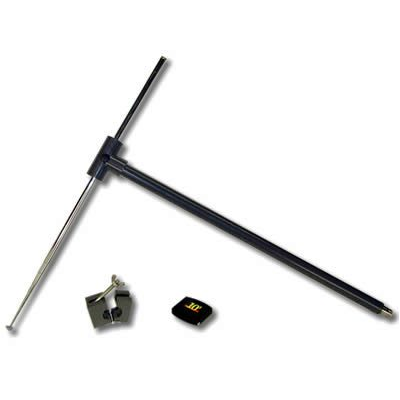
EM TEST CWS 500N2 Continuous Wave Simulator is designed for testing rf conducted immunity to narrowband radiated electromagnetic energy. Apart from the injection probe and the monitoring probe everything is in the box; controller, signal generator, amplifier, directional coupler and RF power measurement of up to three signals in parallel. A built-in RF switch allows to connect and use any external amplifier to extend the system’s capabilities.
The CWS 500N2 is also designed to be used for tests with CDNs and EM clamps for tests according to EN/IEC 61000-4-6 and related standards.
MODEL OVERVIEW
CWS 500N2.2 Continuous Wave Simulator for BCI (Bulk Current Injection) from 9 kHz up to 1 GHz
CWS 500N2.3 Continuous Wave Simulator for BCI (Bulk current injection) from 4 kHz up to 1 GHz
Features
- Most compact equipment
- Supports BCI testing as per various standard requirements
- Basic frequency range 9kHz up to 400MHz
- Extendable frequency range up to 1GHz
- Built-in 100W class A amplifier up to 400MHz
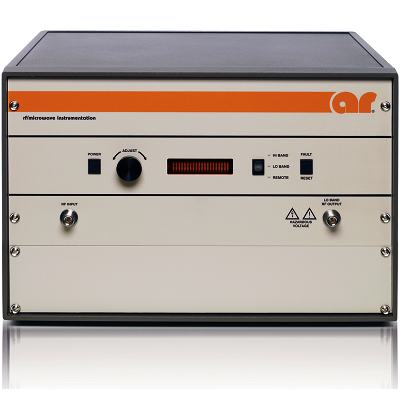
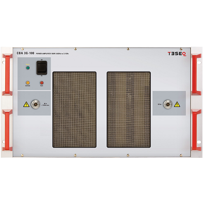
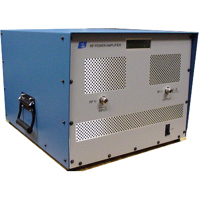
- Built-in RF switch to connect external amplifier
- Built-in directional coupler
- Built-in 3-channel power meter up to 1GHz
 01
01 02
02Specifications
| BULK CURRENT INJECTION AS PER ISO 11452-4 | |
| Output level | As required in ISO 11452-4, using closed loop or substitution method |
| BULK CURRENT INJECTION AS PER MIL 461 CS 114 | |
| Output level | As required in MIL 461 CS 114, using the closed loop method |
| MEASUREMENTS FOR BULK CURRENT INJECTION | |
| Directional coupler | Included to measure forward power and reverse power |
| Forward power | Internal power meter #1 |
| Reverse power | Internal power meter #2 |
| Injected current | Internal power meter #3 |
| TEST ROUTINES FOR BULK CURRENT INJECTION | |
| ISO 11452-4 | Operation via icd.control |
| MIL 461 CS114 | Operation via icd.control |
| IEC 61000-4-6 | |
| Output level | 1V – 30Vrms (emf) all standard test levels are guaranteed with all coupling methods |
| MEASUREMENTS, IEC 61000-4-6 | |
| Cal in (BNC) | Integrated power meter to record the calibration data of a coupling device |
| Injected current | Measured by internal power meter |
| RF indicator | LED indicating the RF output status |
| LCD | Display of the test level and the preselected frequency value |
| OUTPUT | |
| RF output | N connector at the front panel |
| Ouptut power | Built-in amplifier
50dBm (9kHz – 400MHz) at 1dB compression. |
| Gain amplifier | > 50dB |
| Output impedance | 50ohm |
| Harmonic distortion | < -20dBc at max. power |
| Insertion loss | Approx. 1dB (directional coupler + RF relay) |
| GENERAL DATA | |
| Dimensions | 19″/6HU |
| Weight | approx. 31kg |
| Supply voltage | 115V to 230V +10/-15%, 50/60Hz |
| Input power | Max. 380W |
| Power factor | cos (phi) = 0.96 at max. output power as per IEC 555 |
| Fuses | 2 x 6.3AT (115V) or
2 x 3.15AT (230V) |
| Cooling | Active cooling, air ventilation |
| Temperature | 10°C to 40°C |
| Rel. humidity | Max. 85%, non condensing |
- Basic Standards
- IEC 61000-4-6
- MIL-STD
- RTCA DO-160 Section 20
- MIL-STD 461
- MIL-STD 461 CS114
- RTCA DO-160
- Product Standards
- IEC 60601-1-2
- IEC 61326-1
- IEC 61850-3
- Automotive Standards
- ISO 11452-4
- ISO 11452-5
- SAE J1113-4
- Generic Standards
- EN 61000-6-1
- EN 61000-6-2
- Automotive OEM Specifications
- BMW GS 95002
- DaimlerChrysler DC-10614
- DaimlerChrysler DC-11224
- Fiat 9.90110
- Ford ES-XW7T-1A278-AB
- Ford ES-XW7T-1A278-AC
- GMW3097
- Mercedes-Benz MBN 10284-2
- PSA B21 7110
- Renault 36.00.808
- International Standards
- VG 95373-24