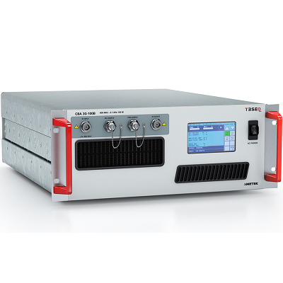
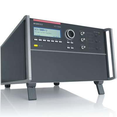
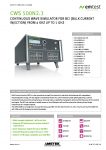
EM TEST CWS 500N2.3 Continuous Wave Simulator
Description
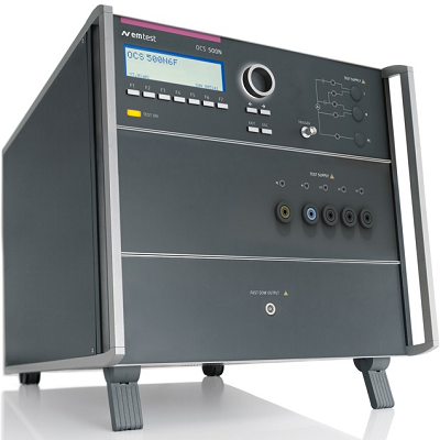
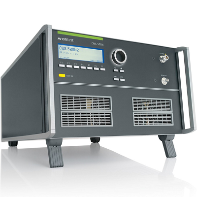
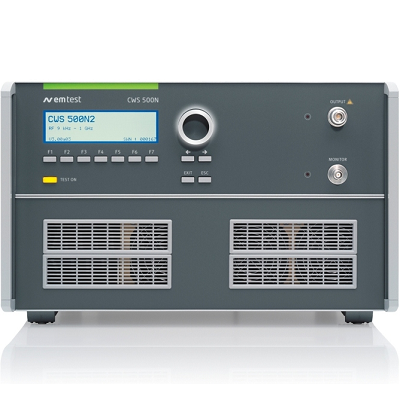
CWS 500N2.3 Continuous Wave Simulator for BCI (Bulk Current Injection) from 4 kHz up to 1 GHz
EM TEST CWS 500N2.3 Continuous Wave Simulator is designed for testing RF conducted immunity to narrowband radiated electromagnetic energy starting from 4 kHz up to 400 MHz.
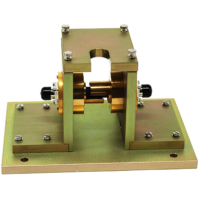
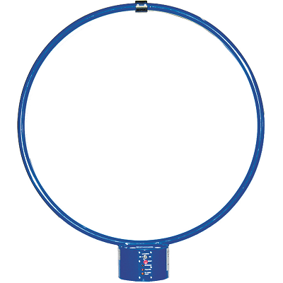
The BCI test method is widely known in the military/aircraft and the automotive industry to test single components of a complex system. The CWS 500N2.3 is used for tests as per MIL STD 461 D/E/F/G CS 114, ISO 11452-4 and IEC/EN 61000-4-6 with CDNs and EM clamps and related standards.
The compact CWS 500N2.3 is a very flexible solution and can be used in the laboratory as well as everywhere in the field.
MODEL OVERVIEW
CWS 500N2.2 Continuous Wave Simulator for BCI (Bulk Current Injection) from 9 kHz up to 1 GHz
Features
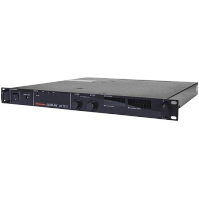
- Most compact equipment – all-in-one box
- Supports BCI testing as per various standard requirements
- Basic frequency range 9 kHz up to 400 MHz
- Extended frequency range 4 kHz up to 1 GHz
- Built-in 110 W class A amplifier up to 400 MHz
- Built-in RF switch to connect external amplifier
- Built-in directional coupler
- Built-in 3-channel power meter up to 1 GHz
 01
01 02
02Specifications
| TECHNICAL DETAILS | |
| OUTPUT | |
| RF output | N connector at the front panel |
| Output power | Built-in amplifier 110 W (nominal) |
| Gain amplifier | > 50 dB |
| Output impedance | 50 ohm |
| Harmonic distortion | < -20 dBc at max. power |
| Insertion loss | Approx. 1 dB (directional coupler + RF relay) |
| SIGNAL GENERATOR | |
| Output level | -63.5 dBm to 0 dBm |
| Frequency range | 4 kHz to 1 GHz |
| Output impedance | 50 ohm |
| Direct RF output | To control an external amplifier |
| TEST FREQUENCIES | |
| Frequency range | 4 kHz* – 400 MHz (built-in amplifier)
4 kHz* – 1,000 MHz (ext. amplifier) |
| Unmodulated signal | CW (continuous wave) |
| Amplitude modulation | Frequency: 1 Hz to 3,000 Hz, Index: 1% to 95%, |
| Pulse modulation | Frequency: 1 Hz to 3,000 Hz Index: 10% to 80% |
| * | 4 kHz with optional IMNS1-CWS
Impedance matching network, otherwise 9 kHz to 1 GHz |
| DUAL DIRECTIONAL COUPLER | |
| Dual directional coupler | Included to measure forward power and reverse power |
| Frequency range | 4 kHz* to 1 GHz |
| Power | 200 W max. |
| Insertion loss | 0.6 dB max. |
| Mainline VSWR | 1.1:1 max. |
| MEASUREMENT | |
| PM 1000.1 | 3-channel power meter 4 kHz to 1 GHz |
| Forward power | Internal power meter #1, -10 dBm to +52 dBm |
| Reverse power | Internal power meter #2, -10 dBm to +52 dBm |
| Injected current (Monitor) | Internal power meter #3, -45 dBm to +13 dBm |
| TIME PARAMETERS | |
| Dwell time | td = 0.3 s – 9,999 s |
| Pause time | tr = 0/0.3 s – 9,999 s |
| INTERFACE | |
| Serial interface | USB |
| Parallel interface | IEEE 488, addresses 1 – 30 |
| Fail 1 | BNC input; test will be stopped (active low) |
| Fail 2 | BNC input; test status will be saved (max. 10 events) when active low. Test continues |
| GENERAL DATA | |
| Dimensions, weight | 19″/6 HU, 31.6 kg |
| Supply voltage | 115 V or 230 V +10/-15 %, 50/60 Hz |
| Input power | Max. 1430 W Inrush |
| Power factor | cos(phi) = 0.96 at max. output power as per IEC 555 |
| Fuses | 2×6.3 AT (115 V) or 2×6.3 AT (230 V) |
- Basic Standards
- IEC 61000-4-6
- MIL-STD
- RTCA DO-160 Section 20
- MIL-STD 461
- MIL-STD 461 CS114
- RTCA DO-160
- Product Standards
- IEC 60601-1-2
- Automotive Standards
- ISO 11452-4
- ISO 11452-5
- SAE J1113-4
- Generic Standards
- EN 61000-6-1
- EN 61000-6-2
- Automotive OEM Specifications
- Fiat 9.90110
- Ford EMC-CS-2009.1
- Ford ES-XW7T-1A278-AC
- Ford FMC1278