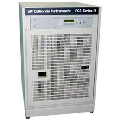
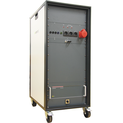
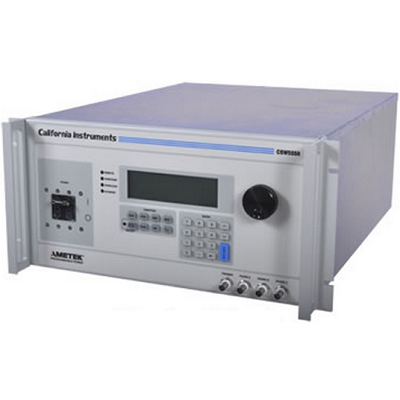
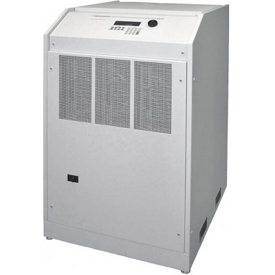
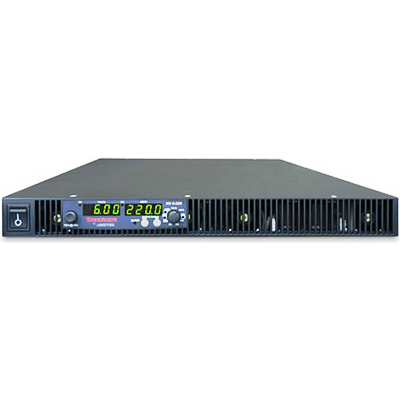
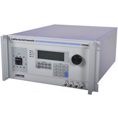
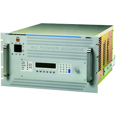
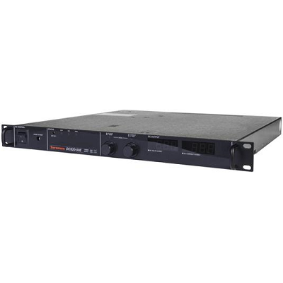
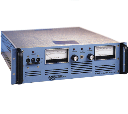
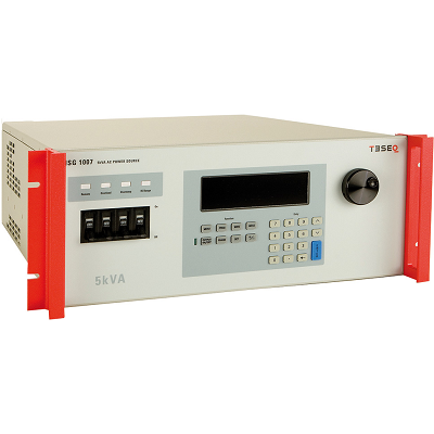
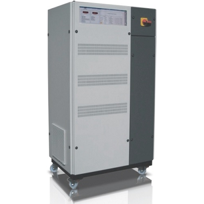
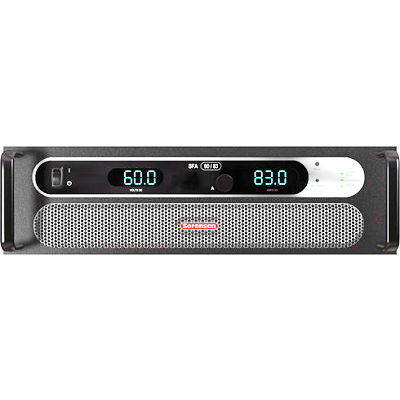
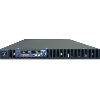
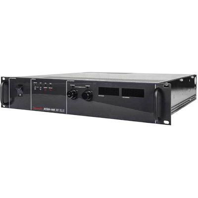
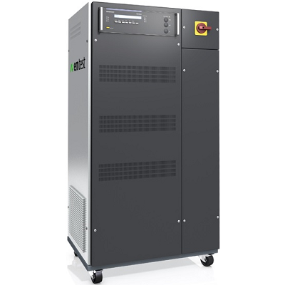
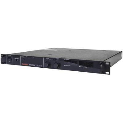
California Instruments FCS Series II AC Power Supply 18kVA – 54kVA
Description
The FCS Series provides high output single or three phase power. It is used primarily for facility wide AC power delivery or high power test applications. Three phase systems top out at 54,000 VA, single phase systems at 72,000 VA. FCS systems come in a compact, low center of gravity cabinet that can be moved around easily to different locations. Using a highly efficient pulse width modulation DC/DC converter design, the FCS series delivers more power with higher efficiency than comparable AC power systems. Both manual oscillators and programmable controllers are available for the FCS Series of AC amplifiers. Programmable controllers offer Line Disturbance Simulation (LDS) and transients for product test applications. Options for MIL-STD704D and RTCA-DO160 tests are available for avionics applications requiring high levels of output power.
Features
- 18 kVA to 54 kVA of AC Output Power
- Front Panel Configurable for Single or Multi-Phase Operation
- Voltage and Frequency Programmable Over IEEE-488 Bus
- Full Power Line Disturbance Simulation Available
- Drives Non-Linear Loads and High Peak In-Rush Current Input Stages
- High Performance
135/270 V, 156/312 V, or 200/400 V - Easy to Program
Uses front panel keyboard display with full decimal keypad for data entry - Single or Three Phase Operation
Ideally suited for avionics and defense applications - Arbitrary Waveform Capability
Test products for harmonics susceptibility - Power Analyzer
Performs voltage and load current harmonic analysis and waveform acquisition - Features multiple Connectivity
Connects via RS232, USB, and GBIB – remote control interface for ATE system integration included
Specifications
|
Input |
||
|
Maximum Power per phase |
FCS18-1 (1 phase): 18 kVA; FCS18-3 (3 phase): 6 kVA |
|
|
Power factor |
0 to unity at full output VA |
|
|
Voltage Ranges |
||
|
Range |
VLow |
VHigh |
|
AC |
0 – 135 V |
0 – 270 V |
|
VA Programming Resolution |
100 mV |
|
|
Load Regulation |
< 0.1 % FS |
|
|
Line Regulation |
< 0.02 % for 10 % line change |
|
|
See -HV and EHV options for alternative voltage range pairs. |
||
|
Programming Accuracy |
± (0.05% + 0.25 V) from 10V to FS. Specified at voltage sense point with ALC mode ON. |
|
|
Frequency Range |
45 Hz – 1200 Hz (see -HF option for higher output frequencies) |
|
|
Frequency Resolution |
0.01 Hz at < 81.9 Hz, |
|
|
Max RMS Current |
||
|
Range |
FCS18-1 |
FCS18-3 |
|
0 – 135 V |
133.2 Arms |
44.4 Arms |
|
0 – 270 V |
66.6 Arms |
22.2 Arms |
|
Note: Constant power mode on the FCS Series II provides increased current at reduced voltage |
||
|
Current Limit |
Programmable from 0 Amps to maximum current for selected range |
|
|
Peak Current |
5.7 X (lrms @ full scale voltage) |
|
|
Output Noise |
100mV rms typ. (20 kHz to 1 MHz) |
|
|
Isolation Voltage |
300 V rms output to chassis |
|
|
Harmonic Distortion |
< 1% (at full scale voltage, full resistive load) |
|
|
Output Relay |
Push button controlled and bus controlled output relay |
|
|
Input |
||
|
Line Voltage/Current (rms per phase) |
||
|
Models |
Line Voltage |
Line Current |
|
208 VAC (STD) |
± 10% |
65 Arms |
|
240 VAC (OPT) |
± 10% |
56 Arms |
|
380 VAC (OPT) |
± 10% |
36 Arms |
|
415 VAC (OPT) |
± 10% |
33 Arms |
|
480 VAC (OPT) |
± 10% |
28 Arms |
|
Line VA |
24 KVA at nominal input voltage |
|
|
Line Frequency |
47-63 Hz |
|
|
Efficiency |
85% (Typical) depending on line and load |
|
|
Power Factor |
0.85 (Typical) |
|
|
Inrush Current |
250 Apk max. (Note: Each FCS chassis requires its own AC service) |
|
|
Hold-up Time |
> 10 ms |
|
|
Isolation Voltage |
400 VAC RMS input to output; 1350 VAC input to chassis |
|
|
Measurement |
||
|
Voltage |
Resolution 0.1 Volt, Accuracy 0.05% + 0.25%, Range 0 – 400 V |
|
|
Current |
Resolution 0.01 Amp, Accuracy 0.1% + 0.15A, Range 0 – 20 Amps |
|
|
Power |
Resolution 0.01 kW, Accuracy 1.0 % FS, Range 0 – 54 KW |
|
|
Phase Angle |
Resolution 0.1°, Accuracy ± 2°, Range 0 – 360 ° |
|
|
Power Factor |
Range 0.00 to 1.00 |
|
|
Frequency |
Resolution four decades, Accuracy ± 0,02 Hz to 99.99 Hz, ± 0.2 Hz to 500.0 Hz, ± 0.5 Hz to 999.9 Hz, |
|
|
Apparent Power |
Resolution 0.01 kVA, Accuracy 1.0 % FS, Range 0 – 54 KVA |
|
|
Protection |
||
|
Overload / Temp / Voltage |
Overload: Constant current or constant voltage mode; Over temperature: Automatic Shutdown; Over voltage: Surge protection to withstand EN50082-1 (IEC 801-4, 5) levels. |
|
|
Regulatory / RFI Suppression |
IEC1010, EN50081-2, EN50082-2, CE, EMC, and safety mark requirements / RIF Suppression: CISPR 11, Group1, Class A |
|
|
System |
||
|
Storage |
Setup: 16 complete instrument setups / Transient List: 100 transient steps per list (SCPI mode) or 16 transient registers (APE mode) |
|
|
Trigger Input / Output |
Input: Triggers measurements or transient steps – SMA connector: 10K pull-up / Output: SMA Connector: HCTTL output |
|
|
Remote Control |
||
|
IEEE-488 Interface (option) |
IEEE-488 (GPIB) talker listener. Subset: AH1, C0, DC1, DT1, L3, PP0, RL2, SH1, SR1, T6, IEEE-488.2 SCPI Syntax |
|
|
USB Interface & Ethernet |
Version: USB 1.1; Speed: 460 Kb/s maximum / Ethernet Interface (Optional): specify -LAN option. 10BaseT, 100BaseT, RJ45 |
|
|
RS232C Interface |
Bi-directional serial interface; 9-pin D-shell connector. Handshake: CTS, RTS. Databits: 7 w/ parity, 8 w/o parity. Stopbits: 2. Baud rate: 9600 to 115200. Supplied with RS232C cable / Code and Format: SCPI; APE (option -GPIB) |
|
|
Physical Dimensions |
||
|
Dimensions (per chassis) |
Height: 45” (114.3 cm), Width: 30” (76.2 cm), Depth: 36” (+ 4” for J-box) = 40” (101.6 cm) (For /2 or /3 models multiply height by 2/3) |
|
|
Weight |
Chassis: Net: 900 lbs / 87.7 Kg, Shipping: 1100 lbs / 127.3 Kg (for /2 or /3 model configurations multiply number of chassis). |
|
|
Vibration and Shock |
Designed to meet NSTA project 1A transportation leveI |
|
|
Air Intake/Exhaust |
Forced air cooling, front to rear air intake, rear exhaust, variable fan speed |
|
|
Temperature |
Operating: 0 to 35° C, full power / Storage: -40 to +85° C |
|
|
Diagnostics |
Built-in self test available over bus (*TST) |
|
|
Rear Panel Connectors |
* Three phase AC input and output terminal block with safety cover. * IEEE-488 (GPIB) connector, USB connector, RJ45 connector (with -LAN Option). * 9-pin D-Shell RS232C connector (RS232 DB9 to DB9 cable supplied). * Remote Inhibit (INH) and Discrete Fault Indicator (DFI). * Remote voltage sense terminal block. * Trigger In1 and Trigger Out1. * System interface connectors. * Auxilary Output |
|
