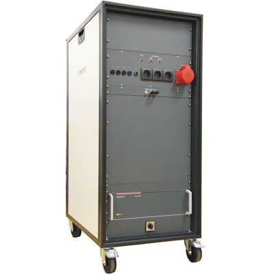
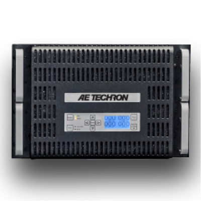
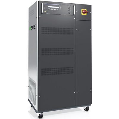
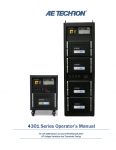
AE Techron 4301-series Telecom Test Systems for GR-1089 Section 10
Description
AE Techron 4301 Series Telecom Test Systems have been specially designed for EMC testing of network telecommunications equipment and for producing the waveforms required for transient voltage measurements as described in GR-1089 Section 10 and ATIS-0600315.2007.
MODEL OVERVIEW
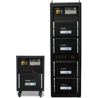
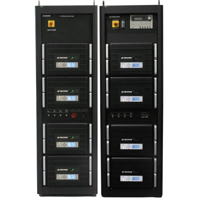
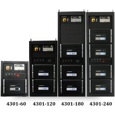
4301-60 Telecom Test System 60A for GR-1089 SECTION 10
4301-120 Telecom Test System 120A for GR-1089 SECTION 10
4301-180 Telecom Test System 180A for GR-1089 SECTION 10
4301-240 Telecom Test System 240A for GR-1089 SECTION 10
Features
- Slew rates up to 60 V/µsec
- Up to 240A DC at +50VDC or –50VDC (4301-240 configuration)
- Can provide pulses of up to 800 amps at voltages of up to ±100V (4301-240 configuration)
- Adjustable compensation allows the system to maintain a 50V/2 µsec rise-time over a wide range of current outputs
 01
01 02
02 03
03 Download Data Sheet
Print
Email
Specifications
| Performance | |
| Maximum Continuous DC Current (±50VDC) | |
| 4301-60 | 60A |
| 4301-120 | 120A |
| 4301-180 | 180A |
| 4301-240 | 240A |
| Maximum Pulse DC Current (up to ±100VDC) | |
| 4301-60 | 200A |
| 4301-120 | 400A |
| 4301-180 | 600A |
| 4301-240 | 800A |
| Voltage Gain | 20 |
| Maximum Input Voltage | ±10V, unbalanced |
| Indicators and Controls (4301 system amplifier modules) | |
| LED Displays | Indicators for Run, Ready, Standby, and Stop status, and Fault conditions in the output stage. |
| LCD Display | Can be user-configured for up to four simultaneous displays reporting one, two, or all four of the following: Voltage Peak, Voltage RMS, Current Peak and Current RMS. When the amplifier module is in a Fault condition, the LCD Display lists the type of fault condition and gives suggested corrective action. |
| Navigation Buttons | The Navigation Buttons provide four arrow keys to allow navigation through the various LCD display options. |
| Soft Touch Switches | Soft touch switches allow the selection of Run (Enable), Stop and Reset functions. |
| Compensation Setting | A four-position rotary control allows the selection of optimum compensation settings according to the total current required at the system output. |
| Compensation LEDs | When the amplifier module is receiving AC power, the colored LED associated with the selected Compensation setting will be lit. |
| Inputs and Outputs | |
| Signal Input | A BNC connector located on the cabinet front input/output panel accepts input from an arbitrary waveform generator. |
| External Trigger Output | A BNC connector located on the cabinet front input/output panel provides the signal to the Trigger In connector on the AWG. |
| Current Monitor Output: | A BNC connector located on the cabinet front input/output panel provides scaled voltage output for current monitoring: |
| 4301-60 | 20A output = 1V monitor output. |
| 4301-120 | 40A output = 1V monitor output. |
| 4301-180 | 60A output = 1V monitor output. |
| 4301-240 | 80A output = 1V monitor output. |
| 4301-60 | 20A output = 1V monitor output. |
| Voltage Monitor Output | A BNC connector located on the cabinet front input/output panel provides scaled voltage output for voltage monitoring: 10V output = 1V monitor output. |
| Signal Output | 250A Pin Plug connectors (or optional Anderson SB350 connectors) provide signal output to the equipment under test. |
| Protection | |
| Fault | The Fault LED on an amplifier module will light if the module’s output stage stops operating. If this happens, contact AE TECHRON for servicing information. |
| AC Under/Over Voltage Protection:
|
If the AC line voltage rises or drops more than10% of the nominal operating voltage, the system will be forced to Standby. |
| Over Current
|
Each amplifier module contains breaker protection on both the unit’s main power supply and the low-voltage supplies. The 4301 system provides a Main Power breaker switch and an Auxiliary Power breaker switch located inside the cabinet rear door. |
| Over Temperature | Each amplifier module contains separate output transistor, heat-sink and transformer temperature monitoring and protection circuits. |
| Operating Temperature | 10°C to 50°C (50°F to 122°F), Maximum Output Power de-rated above 30°C (86°F).) |
| Humidity | 70% or less, non-condensing |
| Dimensions (H x W x D) | |
| 4301-240 and 4301-180 | 74 in. x 22 in. x 31.5 in. (188 cm x 55.9 cm x 80 cm). |
| 4301-120 and 4301-60 | 52 in. x 22 in. x 31.5 in. (132 cm x 55.9 cm x 80 cm). |
| Net Weight | |
| 4301-240 | 1050 lbs. (476 kgs) |
| 4301-180 | 897 lbs. (316 kgs) |
| 4301-120 | 589 lbs. (267 kgs) |
| 4601-60 | 436 lbs. (198 kgs) |