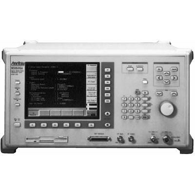
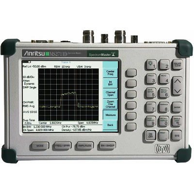
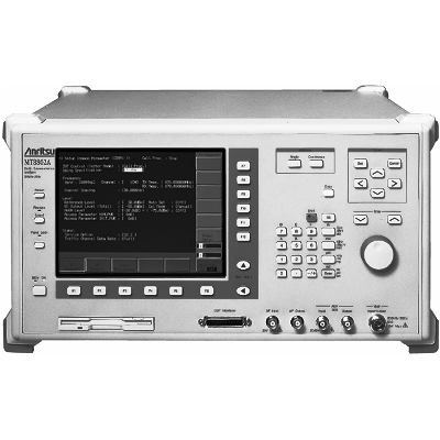
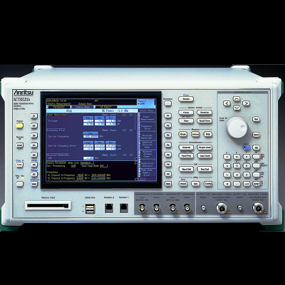
Anritsu MS8606A Digital Mobile Transmitter Tester 300 kHz - 3 GHz
Description
The MS8606A can measure CDMA (IS-95, ARIB STD-T53) forward and reverse transmission characteristics. It is ideal for measuring transmitter characteristics including frequency, waveform quality, timing error, code domain power, transmitter power, occupied bandwidth, neighboring spurious, etc. The MS8606A can measure PDC transmission characteristic such as transmission frequency and power, modulation accuracy, occupied bandwidth, and adjacent channel power, in addition to the bit error rate.
The built-in spectrum analyzer covers frequencies of 10 MHz to 3GHz making it ideal for R&D. In addition, the general-purpose evaluation functions can be used to measure the adjacent channel power, occupied bandwidth, and sideband noise of radio equipment. The MS8606A has general-purpose analog measurement functions, including frequency counter, power meter, FM/øM measurement, AF oscillator and audio analyzer, making it perfect for FM radio transmission tests (AF oscillator and audio analyzer optional).
Features
- For CDMA, PDC measurement
- High-speed, high precision measurement
- Built-in spectrum analyzer and AF measurement function
Specifications
|
Frequency Range |
300 kHz to 3 GHz |
|
Max. Input |
level MAIN connector: +40 dBm (10 W), AUX connector: +20 dBm (100 mW) |
|
Input Impedance |
50 ½, VSWR: ²1.2 (²2.2 GHz, MAIN connector), ²1.3 (>2.2 GHz, MAIN connector) |
|
Input Connector |
N-type (MAIN connector), TNC-type (AUX connector) |
|
Frequency |
10 MHz |
|
Reference oscillator |
Starting Characteristics ²5 x 10⁻⁸/day (after 10 minutes of warm-up, compared to the frequency after 24-hour warm-up) |
|
Aging rate: ²2 x 10⁻⁸/day, ²1 x 10⁻⁷/year (compared to the frequency after 24-hour warm-up) |
|
|
Temperature characteristics: ²5 x 10⁻⁸ (compared to the frequency at 25°C) |
|
|
External reference input: 10 or 13 MHz (±1 ppm), 2 to 5 Vp-p |
|
|
Frequency range: 300 kHz to 3 GHz |
|
|
Power meter |
Level range: 0 to +40 dBm |
|
Measurement accuracy: ±10% (after zero calibration) |
|
|
Frequency |
Frequency setting |
|
Setting range: 0 to 3 GHz (band: 0), 10 MHz to 3 GHz (band: 1), Setting resolution: 1 Hz |
|
|
Frequency accuracy |
|
|
Display accuracy: ±(display frequency x reference frequency accuracy + span x span accuracy) |
|
|
Normal marker: Same as display frequency accuracy |
|
|
Delta marker: Same as span accuracy |
|
|
Frequency span |
|
|
Frequency Setting range: 0 Hz, 10 kHz to 3 GHz (band: 0); 0 Hz, 10 kHz to 2.99 GHz (band: 1) |
|
|
Span accuracy: ±2.5% |
|
|
RBW (resolution bandwidth) |
|
|
Setting range: 300 Hz to 1 MHz (3 dB BW, 1-3 sequence) |
|
|
Accuracy: ±2% (300 Hz to 300 kHz), ±10% (1 kHz) |
|
|
Selectivity (60 dB : 3 dB): ²5:1 |
|
|
VBW (video bandwidth): 3 Hz to 100 kHz (1-3 sequence), through |
|
|
Side band noise: ²–95 dBc/Hz (1 GHz, 10 kHz offset), ²–115 dBc/Hz (1 GHz, 100 kHz offset) |
|
|
Amplitude (at Band: 1) |
Maximum input level |
|
Continuous average power: +40 dBm (MAIN connector), +20 dBm (AUX connector) |
|
|
DC voltage: 0 V |
|
|
Average noise level (at RBW: 1 kHz, VBW: 10 Hz): |
|
|
²–90 dBm (MAIN connector, 10 MHz to 1 GHz, input attenuator: 20 dB) |
|
|
²–90 dBm + f[GHz] (MAIN connector, >1 GHz, input attenuator: 20 dB) |
|
|
²–110 dBm (AUX connector, 10 MHz to 1 GHz, input attenuator: 0 dB) |
|
|
²–110 dBm + f[GHz] (AUX connector, >1 GHz, input attenuator: 0 dB) |
|
|
Residual response: ²–70 dBm (MAIN connector, input attenuator: 20 dB), ²–90 dBm (AUX connector, input attenuator: 0 dB) |
|
|
Total level accuracy |
|
|
MAIN connector: ±1.5 dB (reference level: +10.1 to +40 dBm, at 0 to –50 dB of reference level) |
|
|
Amplitude (at Band: 1) AUX connector: ±1.5 dB (reference level: –9.9 to +20 dBm, at 0 to –50 dB of reference level) |
|
|
Reference level |
|
|
Setting range: –50 to +50 dBm (MAIN connector), –75 to +30 dBm (AUX connector) |
|
|
Setting resolution: 0.1 dB |
|
|
Accuracy: ±0.5 dB (MAIN connector, +10.1 to +40 dBm), ±1.0 dB (MAIN connector, –50 to +10 dBm) |
|
|
±0.5 dB (AUX connector, –9.9 to +20 dBm), ±1.0 dB (AUX connector, –75 to –10 dBm) |
|
|
RBW switching error: ±0.1 dB (referenced to RBW: 3 kHz) |
|
|
Frequency response: ±0.5 dB [referenced to 100 MHz, input attenuator: 30 dB (10 dB for AUX); temperature range: 18 to 28°C] |
|
|
Log linearity: |
|
|
±0.5 dB (0 to –50 dB, RBW: ²1 MHz), ±1.0 dB (0 to –70 dB, RBW: ²30 kHz), ±1.0 dB (0 to –80 dB, RBW: ²3 kHz) |
|
|
*10 MHz to 2.2 GHz, reference level: ³0 dBm (MAIN connector); ³–20 dBm (AUX connector) |
|
|
2nd harmonic distortion: ²–55 dBc (10 to 100 MHz), ²–60 dBc (100 to 1500 MHz) *At mixer input level: –30 dBm |
|
|
Sweep |
Setting range: 100 ms to 1000 s (frequency axis sweep), 100 ms to 1000 s (time axis sweep, RBW: ²1 kHz) |
|
10 ms to 1000 s (time axis sweep, RBW: 3 to 10 kHz), 1 ms to 1000 s (time axis sweep , ³30 kHz) |
|
|
Trigger switch: FREERUN, TRIGGERED |
|
|
Trigger source: WIDE IF VIDEO (3 dB bandwidth: ³20 MHz, trigger slope: RISE/FALL) |
|
|
Sweep EXT (trigger level: TTL level, trigger slope: RISE/FALL) |
|
|
Trigger delay |
|
|
Setting range: 0 μs to 100 ms, Resolution: 2 μs |
|
|
Gate delay, gate width |
|
|
Setting range: 2 μs to 100 ms, Resolution: 2 μs |
|
|
Functions |
Marker |
|
Signal search: PEAK®CF, PEAK®REF |
|
|
Zone marker: NORMAL, DELTA |
|
|
Marker®function: MARKER®CF, MARKER®REF, ZONE®SPAN |
|
|
Peak search: PEAK, NEXT PEAK, NEXT RIGHT PEAK, NEXT LEFT PEAK |
|
|
Measurement |
|
|
Functions Noise power: dBm/Hz, dBm/ch |
|
|
C/N: dBc/Hz, dBc/ch |
|
|
Occupied bandwidth: Power N% method, X dB down method |
|
|
Adjacent channel power |
|
|
Reference measurement: Total power/reference level method, |
|
|
Display method: Channel designate display 2 channels x 2, graphic display |
|
|
Average power of burst signal: Average power within the specified time range of the time axis waveform |
|
|
Others |
Number of data point: 501 |
|
Others Detection mode: POS PEAK, NEG PEAK, SAMPLE |
|
|
Display function: TRACE A, TRACE B, TRACE TIME |
|
|
Storage function: NORMAL, VIEW, MAX HOLD, MIN HOLD, AVERAGE, CUMULATIVE, OVER WRITE |
|
|
RF Analyzer |
Power measurement (wide band) |
|
Frequency range: 300 kHz to 3 GHz |
|
|
Level range: 0 to +40 dBm (MAIN connector) |
|
|
Accuracy: ±10% (after zero point calibration) |
|
|
Power measurement (narrow band) |
|
|
Frequency range: 10 MHz to 3 GHz |
|
|
Input level: 0 to +40 dBm (MAIN connector), –40 to +20 dBm (AUX connector) |
|
|
Accuracy: ±10% (MAIN connector, after calibration with internal wide band power meter) |
|
|
±1 dB (AUX connector, reference level: ³–12 dBm, after calibration) |
|
|
Linearity: ±0.3 dB (0 to –30 dB) |
|
|
Frequency measurement |
|
|
Frequency range: 10 MHz to 3 GHz |
|
|
Input level: –15 to +40 dBm (MAIN connector), –40 to +20 dBm (AUX connector) |
|
|
Resolution: 1 Hz |
|
|
Accuracy: ±(reference oscillator accuracy + 10 Hz) *IF frequency counting (bandwidth: ±30 kHz) |
|
|
FM measurement |
|
|
Frequency range: 10 MHz to 3 GHz |
|
|
RF analyzer Input level: –15 to +40 dBm (MAIN connector), –40 to +20 dBm (AUX connector) |
|
|
Deviation: 0 to 20 kHz |
|
|
Demodulation frequency: 30 Hz to 20 kHz |
|
|
Accuracy: 1% of indicated value + residual FM (demodulation frequency: 1 kHz) |
|
|
Frequency response: ±0.5 dB (demodulation frequency: referenced to 1 kHz) |
|
|
Residual FM: 8 Hz-rms (demodulation frequency: 0.3 to 3 kHz) |
|
|
Distortion: 0.3% (demodulation frequency: 1 kHz, demodulation bandwidth: 0.3 to 3 kHz, deviation: 5 kHz) |
|
|
Filters (3 dB cut-off): HPF (50 Hz, 300 Hz), LPF (3 kHz, 15 kHz) |
|
|
øM measurement |
|
|
Frequency range: 10 MHz to 3 GHz |
|
|
Input level: –15 to +40 dBm (MAIN connector), –40 to +20 dBm (AUX connector) |
|
|
Deviation: 0 to 10 rad |
|
|
Demodulation frequency: 300 Hz to 3 kHz |
|
|
Accuracy: 1% of indicated value + residual øM (demodulation frequency: 1 kHz) |
|
|
Frequency response: ±0.5 dB (demodulation frequency: referenced to 1 kHz) |
|
|
Residual øM: 0.01 rad-rms (demodulation bandwidth: 0.3 to 3 kHz) |
|
|
Distortion: 0.5% (demodulation frequency: 1 kHz, demodulation bandwidth: 0.3 to 3 kHz, deviation: 5 rad) |
|
|
Filters (3 dB cut-off): HPF (50 Hz, 300 Hz), LPF (3 kHz, 15 kHz) |
|
|
Others |
Display: Color TFT-LCD, 7.8”, 640 x 480 dots |
|
Hard copy: Enables data hard copy of the display through a parallel interface (printer: ESC/P compatible printer) |
|
|
Others GPIB: This equipment is specified as a device, can be controlled from external controller (excluding power switch). |
|
|
Interface functions: SH1, AH1, T6, L4, SR1, RL1, PP0, DC1, DT1, C0, E2 |
|
|
Parallel interface: Conform to the Centronics. Outputs printing data to printer. D-sub 25-pin connector (female) |
|
|
RS-232C: All functions except power switch controlled by external controller (baud rate: 1200, 2400, 4800, 9600 bps) |
|
|
Dimensions and Mass |
426(W) x 221.5(H) x 451(D) mm, ²22 kg |
|
Power |
100 to 120/200 to 240 Vac (–15%/+10%, max. voltage: 250 V, automatic voltage switch system), 47.5 to 63 Hz, ²300 VA |
|
Operating Temperature |
0° to 50°C |
