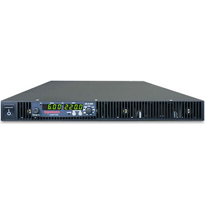
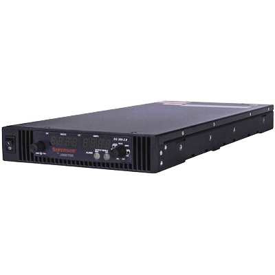
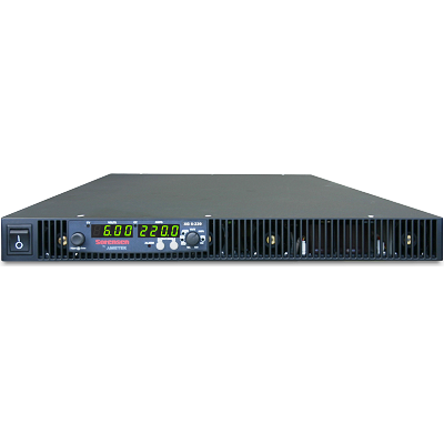
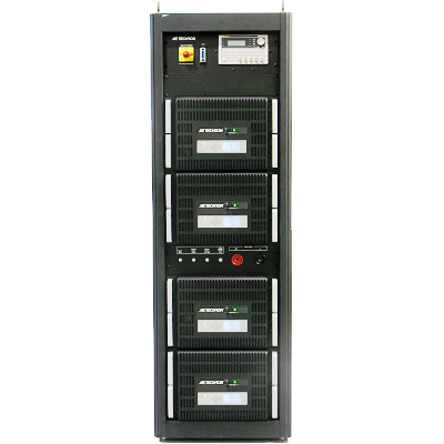
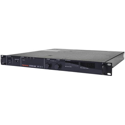
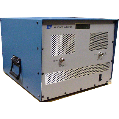
AE Techron 8102 Power Supply Amplifier
Description
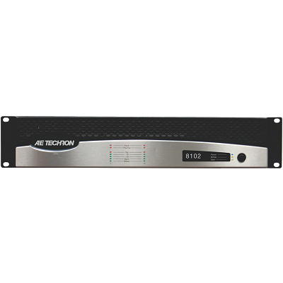
AE Techron 8102 Power Supply Amplifier Single Channel DC Coupled features an advanced switch-mode design that results in low noise and distortion, and high-power density. It is configured as a single-channel, DC-coupled, controlled voltage amplifier ideal for reactive loads. The 8102 can provide up to 16 Arms or 235 Vrms continuous output. It offers a continuous, full-power frequency bandwidth of DC to 5 kHz.
Features
- Up to 16 Arms and 235 Vrms continuous output
- Full-power frequency bandwidth of DC – 5 kHz
- Compact design; only 2U of rack space and 27 lbs
- Switching power supply for reduced weight.
- Installs easily into a standard 19-inch rack or stands alone for bench top operation
- Built-in protection circuitry safely provides for sustained high-power output, with protection against input overloads, improper output connection (including shorts and improper loads), and excessive temperature, voltage or current.
- Operates from single-phase, 120-volt AC mains, (230 VAC version available)
 01
01 02
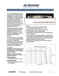
02 Download Data Sheet
Print
Email
Specifications
| Frequency Response | ±3 dB from DC to 5 kHz at 1 watt | |
| Signal to Noise Ratio | < 105 dB (ref. rated power, DC to 5 kHz, A-weighted) | |
| Total Harmonic Distortion (THD) | <0.35% at full rated power, from DC to 5 kHz | |
| I.M. Distortion | <0.35% at 60 Hz and 7 kHz at 41, from -40 dB to full rated power | |
| DC Output Offset | < 15 mV | |
| Input Impedance (nominally balanced, nominally unbalanced) | 10 k ohms, 5 k ohms | |
| Maximum Input Voltage | ± 10 V balanced or unbalanced | |
| Common Mode Rejection (CMR) (20Hz to 1kHz, typical) | 50 dB | |
| Load Impedance | 2 – 62 ohm | |
| Gain Control (when enabled, switch selectable) | Voltage gain adjustable from 20 to 0 or from 63 to 0 | |
| Front Panel Controls and Indicators | ||
| Fault Indicator | Red LEDs, flash when the amplifier output has stopped operating. Usually this means that the amplifier must be serviced | |
| Thermal Indicator | Red LEDs, illuminate when the amplifier has shut down, or is very near shutting down, due to thermal stress or overload | |
| Ready Indicator | Green LEDs, illuminate when the amplifier is initialized and ready to produce output | |
| Input Signal Indicator | Green LEDs, illuminate when the amplifier’s input signal is above –40 dBu (8mVrms) | |
| Output Signal Indicator, -20 dB | Green LEDs, illuminate when the amplifier’s output signal is within 20 dB of clipping | |
| Output Signal Indicator, –10 dB | Green LEDs, illuminate when the amplifier’s output signal is within 10 dB of clipping | |
| Clip Indicator | Red LEDs, illuminate when the amplifier’s output signal reaches the onset of audible clipping. The Clip Indicators also will illuminate during Thermal Level Control (TLC) limiting or when the input compressor/limiter is protecting the amplifier from input overload | |
| Cooling Vents | Front-to-rear forced airflow | |
| Power Indicator | Blue LED indicates AC power has been applied and is within the safe operating range of the power supply. The LED will flash when the AC line voltage is approximately 15% above or 25% below the nominal rated value | |
| Data Indicator | Feature not implemented | |
| Bridge Indicator | Illuminates when the amplifier is receiving AC power | |
| Power Switch | Push-on / push-off switch | |
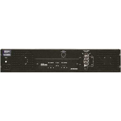
| Back Panel Controls and Connectors | ||
| Power Cord Connector | Standard 15 amp IEC inlet. A circuit breaker located near the IEC power inlet protects the amplifier from excessive AC current draw | |
| Reset Switch | Resets the circuit breaker that protects the power supply | |
| Ventilation Grille | Air flow is front to back. Do not block the ventilation grilles | |
| Input Panel | 8100 Series Input Card includes two balanced 3-pin removable barrier connectors for signal input. The “Y” Input Switch can be used to daisy-chain the input signal to another amplifier. When this switch is set to ON, CH-1 input and CH-2 input are paralleled, reducing input impedance by 50%. Either CH-1 input or CH-2 input can be used when the “Y” Input switch is set to ON | |
| Input Attenuator | One 21-position detented rotary attenuator, ranging from –100 dB to 0 dB gain | |
| Output Connectors | One two-pole touch-proof terminal strip. Accepts up to 10 AWG terminal forks | |
| Output Cover (not shown) | This covers the output connectors, protecting users from the connectors’ potentially high voltage. This cover is required for Class 2 wiring installations | |
| Physical Characteristics | ||
| Required AC Mains (+15%, -25%) | 120V/60Hz (230V/50Hz version available) | |
| Power Draw at Idle (120 VAC mains) | 35W (Standby Mode) | |
| Overall Group Delay | < 120 sec | |
| Operating Temperature | 10°C to 50°C (50°F to 122°F), Maximum Output Power de-rated above 30°C (86°F).) | |
| Humidity | 70% or less, non-condensing | |
| Cooling | Front-to-back airflow | |
| Chassis | The Amplifier is designed for stand-alone or rack-mounted operation. The Chassis is black aluminum with a powder coat finish. The unit occupies two EIA 19-inch-wide units | |
| Dimensions | Width | 19 inches (48.3 cm) |
| Height | 3.5 inches (8.9 cm) | |
| Depth | 14.25 inches (36.2 cm) | |
| Net Weight | 27.0 lbs. (12.3 kgs) | |
| Shipping Weight | 32.0 lbs. (14.5 kgs) | |
| Protection | ||
| Fault | The amplifier will light the Fault LED if the amplifier output stage stops operating. If this happens, contact AE TECHRON for servicing information | |
| Low-Pass Filters | Gaussian-approximation ultrasonic filters prevent ultrasonic feedback and HF burnout of transducers. This type of filter preserves transient response better than a Butterworth filter | |
| AC Under/Over Voltage Protection | If the AC line voltage drops below 25% or rises above 10% of the nominal operating voltage of the amplifier, the amplifier’s blue Power LED flashes. The LED will stop flashing and return to solid ON when the AC line voltage returns to safe operating levels | |
| Circuit Breaker | A circuit breaker located near the IEC power inlet protects the amplifier from excessive AC current draw | |
| Inrush Limiting | A soft-start circuit in the power supply minimizes the amplifier’s current draw during power-on | |