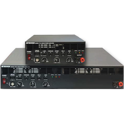
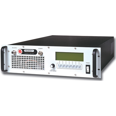
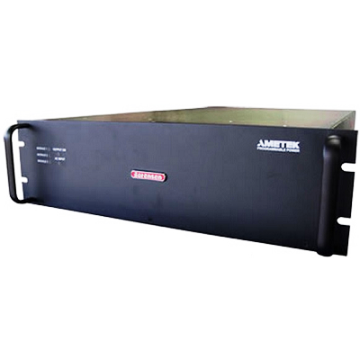
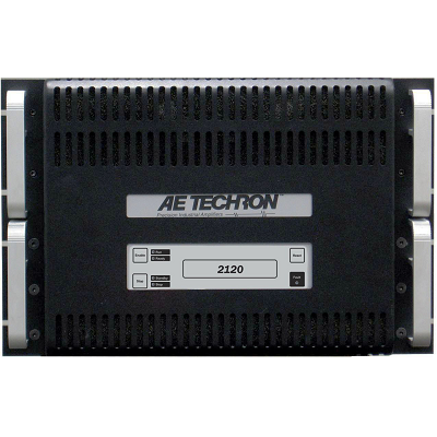
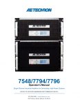
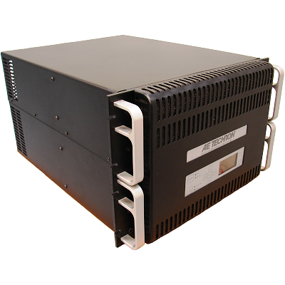
AE Techron 7794 Power Amplifier DC – 30 kHz 5kW for MIL-STD 704
Description
AE Techron 7794 Power Amplifier DC – 30 kHz is a powerful four-quadrant amplifier that offers up to 200 Ap power and controlled-current or controlled-voltage modes of operation. The 7794 works best into loads of 0.5 ohms or less. For greater voltage or current (up to 800 Ap) units can be combined in parallel or series.
Typically used when large currents are needed to drive very low impedance for long periods of time. Often used as a battery substitute for transient immunity testing requiring a battery as specified in EMC Test Standards for Military, Aerospace and the Automotive industries.
MODEL SERIES OVERVIEW
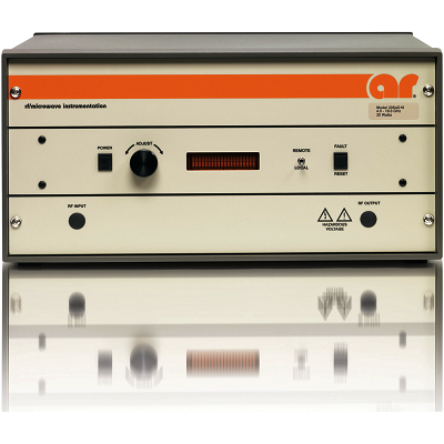
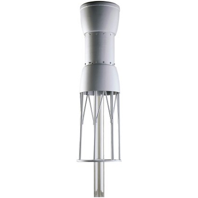
7700-series EMC RF Power Amplifiers DC – 250 kHz, 5 – 20kW, Three Phase for Conducted Immunity Testing
Features
- 60A continuous at 13.8 VDC
- 200A in-rush current capability
- 150 kHz small signal bandwidth
- ±95 VDC capable
- 41 V/µS slew rate
- Four-quadrant operation (source and sink)
 01
01 02
02 03
03 04
04 Download Data Sheet
Print
Email
Specifications
| Performance | |
| Frequency Response, DC – 30 kHz (1 watt) | |
| DC to 50 kHz | +0.1 to -0.5 dB |
| DC to 150 kHz | ± 95 Vpk |
| DC to 200 kHz | ± 25 Vpk |
| Maximum Continuous Output Power | 5000 watts RMS |
| Slew Rate | 41 V/µSec |
| Residual Noise | |
| Unfiltered | Less than 75 µV |
| Filtered (400 Hz to 30 kHz) | Less than 55 µV |
| Unit to Unit Phase Error | ±0.1 degrees at 60 Hz |
| THD (DC – 30 kHz) | Less than 0.1% |
| Output Offset | Less than 200 µV |
| Output Offset Current | Less than 10 mA DC |
| DC Drift, From Cold to Maximum Operating Temperature | ±400µV |
| After 20 minutes of Operation | ±200µV |
| Output Impedance | 3.2 mOhm in Series with 2.2 µH |
| Phase Response (10 Hz – 10 kHz) | ±8.3 degrees |
| Phase Error | ±0.1 degrees at 60 Hz |
| Input Characteristics | |
| Balanced with ground | Three terminal barrier block connector, 20k ohm differential |
| Unbalanced | BNC connector, 10k ohm single ended |
| Gain | |
| Voltage Mode | 20 volts/volt |
| Current Mode | 20 amperes/volt |
| Gain Linearity (over input signal, from 0.2V to 5V) | |
| DC | 0.0125% |
| AC | 0.030% |
| Max Input Voltage | ±10V, balanced or unbalanced |
| Input Impedance | 20 kΩ differential |
| Input Sensitivity | 3.0V input for 3800W output into 1 ohm (adjustable) |
| Common Mode Rejection Range | -±11 VDC maximum |
| Common Mode Rejection Ratio | 70 dB |
| Status Display, Control, I/O | |
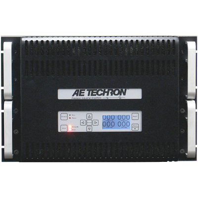
| Front Panel LED Displays indicate | Ready, Standby, Fault |
| Soft Touch Switches for | Run, Stop, Reset |
| LCD Display | Can be configured for up to four simultaneous displays report one, two, or all four of the following: Vp, VRMS, Ap, ARMS |
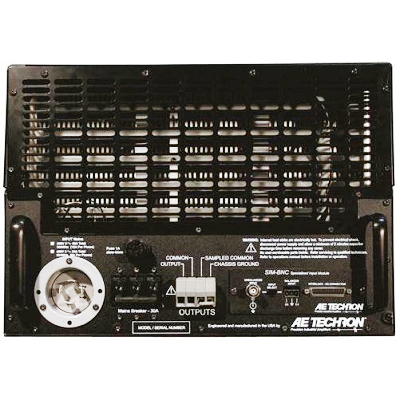
| Back Panel Power Connection | NEMA-style locking receptacle; matching AC connector also included |
| Signal Output | 4-position terminal barrier block (OUTPUT / COMMON / SAMPLED COMMON / CHASSIS GROUND); resistor installed between SAMPLED COMMON AND CHASSIS GROUND is a 2.7-ohm, 2W, 5%, metal-oxide resistor |
| Signal Input | User Selectable BNC or Barrier Strip, Balanced or Unbalanced |
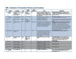
| Interlock Connector | 25-pin D-sub connector used for amplifier control and status applications; also used in multi-amplifier applications |
| Current Monitor | 20A/V ± 1%; 10A/V ± 1% (differential configuration) |
| Reporting | System Fault, Over Temp, Over Voltage, Over Load |
| Remote Control via Interlock Connector | Force to Standby, Reset after a fault |
| Protection | |
| Over/Under Voltage | ± 10% from specified supply voltage amplifier is forced to Standby |
| Over Current | Breaker protection on both main power and low voltage supplies |
| Over Temperature | Separate output transistor, heat sink, and transformer temperature monitoring and protection |
| Physical Characteristics | |
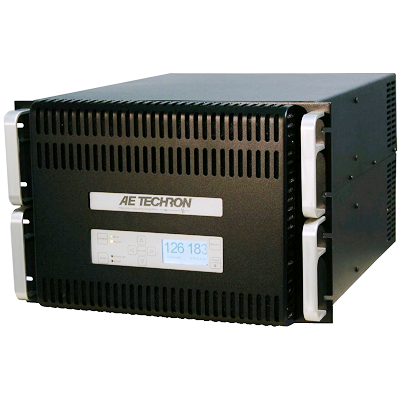
| Chassis | The Amplifier is designed for stand- alone or rack-mounted operation. The Chassis is aluminum with a black powder-coat finish. The unit occupies five EIA 19-inch-wide units. |
| AC Power | Three-phase, 208 VAC (±10%), 47-60 Hz, 30A AC service; (400 VAC (±10%), 15A model available) |
| Weight | 153 lbs. (69 kg), Shipping 168 lbs. (76.2 kg) |
| Dimensions | 19” x 22.8” x 12.25” (48.3 cm x 57.9 cm x 31.3 cm) |
- MIL-STD
- MIL-STD 461
- MIL-STD-704
- RTCA DO-160
- AIRBUS
- BOEING
- Product Standards
- EN 300 329
- EN 300 340
- EN 300 342-1
- EN 301 489-1
- EN 301 489-17
- EN 301 489-24
- EN 301 489-7
- Automotive Standards
- ISO 11452-10
- ISO 11452-8
- ISO 16750-2
- ISO 7637-1
- JASO D001-94
- SAE J1113-11
- SAE J1113-12
- SAE J1113-2
- SAE J1455
- Automotive OEM Specifications
- BMW 600 13.0
- BMW GS 95024-2-1
- Chrysler CS-11809
- Chrysler CS-11979
- DaimlerChrysler DC-10614
- DaimlerChrysler DC-10615
- DaimlerChrysler DC-11224
- DaimlerChrysler PF-10540
- Jaguar EMC-CS-2010JLR v1.2
- Fiat 9.90110
- Ford ES-XW7T-1A278-AB
- Ford FMC1278
- Ford WDR 00.00EA
- Freightliner 49-00085
- GLloyd VI-7-2
- GM 9105P
- GMW3097
- GMW3100
- GMW3172
- Honda 3982Z-SDA-0030
- Hyundai ES 39110-00
- Hyundai/Kia ES 96100-02
- Iveco 16-2103
- Kia/Hyundai ES 95400-10
- Mack Trucks 606GS15
- MAN 3285
- Mazda MES PW 67600
- Mercedes-Benz MBN 10284-2
- Mercedes-Benz MBN 22100-2
- Mercedes-Benz A 211 000 42 99
- Mitsubishi ES-X82010
- MW 3097
- Nissan 28400 NDS 02
- Nissan 28400 NDS 03
- Nissan 28400 NDS 05
- Nissan 28400 NDS 07
- Nissan 28401 NDS 02
- Piaggio 7431
- Porsche AV EMC EN
- PSA B21 7090
- PSA B21 7110
- Renault 36.00.400
- Renault 36.00.808
- SA B21 7110
- Scania TB1400
- Scania TB1700
- Smart DE1005B
- Tata TST/TS/WI/257
- Toyota TSC3500G
- Toyota TSC3590G
- Toyota TSC6203G
- Toyota TSC7001G
- Toyota TSC7034G
- UNECE R10 (Automotive)
- Volvo EMC Requirements
- Volvo STD 515-0003
- Volkswagen VW 80101
- Volkswagen VW TL 820 66
- Volkswagen VW TL 821 66
- Volkswagen VW TL 823 66
- Volkswagen VW TL 824 66
- Volkswagen VW TL 825 66
- Mercedes-Benz AV EMV