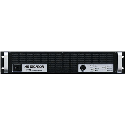
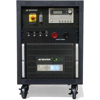
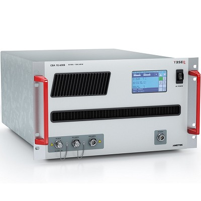
AE Techron 7212 Power Amplifier DC – 250 kHz 440W
Description
AE Techron 7212 Power Amplifier DC – 250 kHz is a four-quadrant, 0.44 kVA, DC-enabled amplifier that was created to meet the exacting requirements of the power utility industry. It features a DC to 250 kHz bandwidth, low noise floor, fast slew rate and a 113V RMS potential. The 7212 can be combined to form a 3-phase Y voltage source, and has a wide range of field-configurable options.
A single 7212 can output a 40 mSec pulse with up to 30 amperes peak current. In continuous operation, a 7212 can provide 440 watts RMS of output power. If more voltage is needed, up to four amplifiers can be combined in series and operate as a single system.
The 7212 can operate in either voltage or current mode and can be configured by the customer for high-voltage/low-current, medium voltage and current, or low- voltage/high-current applications. It provides very low noise and fast slew rates, and can safely drive a wide range of resistive or inductive loads.
Features
- Up to 113V RMS at up to 4A
- Pulsed output up to 30 Ap
- 430 watts RMS continuous output
- Low noise floor of only 300 µV
- Fast, 50 V/µs slew rate
- System output of over 1,700 watts is possible with multiple, interconnected amplifiers
Specifications
| Performance | AC testing was performed at 1 kHz. | |
| Frequency Response, DC—100 kHz (1 watt) | +0.0 to -3.0 dB | |
| 8-Ohm Power Response (continuous duty) | DC to 60 kHz | ± 140 Vpk |
| DC to 100 kHz | ± 50 Vpk | |
| Slew Rate | 50 V/μSec | |
| Residual Noise | 10 Hz to 300 kHz | 950 μV (0.95 mV) |
| 10 Hz to 80 kHz | 300 μV (0.3 mV) | |
| Signal-to-Noise Ratio | 10 Hz – 30 kHz | –113 dB |
| 10 Hz – 80 kHz | –106.6 dB | |
| Unit to Unit Phase Error | ±0.1 degrees at 60 Hz | |
| THD (DC – 30 kHz) | <0.1% | |
| Output Offset | <±5 mV, field adjustable to less than 1 mV | |
| DC Drift | <±1.5 mV | |
| Output Impedance | 5.3 mOhm in Series with 0.95 μH | |
| Phase Response (10 Hz – 10 kHz) | ±5 degrees plus 560 nsec propagation delay | |
| Input Characteristics | Balanced with ground | Three terminal barrier block connector, 20k ohm differential |
| Unbalanced | BNC connector, 10k ohm single ended | |
| Gain (variable or fixed) | Voltage Mode | 20 volts/volt |
| Current Mode | 5 amperes/volt | |
| Gain Linearity (over input signal, from 0.2V to 5V) | 0.15% | |
| Max Input Voltage | ±10V, balanced or unbalanced | |
| Input Impedance | 20k ohm differential | |
| Common Mode Rejection | –58 dB with 5V input | |
| Display, Control, Status, I/O | ||
| Front Panel LED Displays indicate | Ready, Standby, Fault, Over Temp, Over Voltage, Overload | |
| Soft Touch Switches for | Run, Stop, Reset | |
| Gain Control, when enabled | Voltage gain adjustable from 20 to 0 | |
| On/Off Breaker | ||
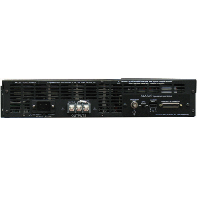
| Back Panel Power Connection | 25 Amp IEC (with retention latch) | |
| Signal Output | Three-position terminal strip (OUTPUT/COM/CHASSIS GROUND); resistor between COM and CHASSIS GROUND terminals is a 2.7-ohm, 2W, 5%, metal-oxide resistor | |
| Signal Input | User-selectable BNC or Barrier Strip, Balanced or Unbalanced | |
| Communication Capabilities | ||
| Current Monitor | 5A/V ± 1%; 2.5A/V ± 1% (differential configuration) | |
| Reporting | System Fault, Over Temp, Over Voltage, Over Load | |
| Remote Control via Interlock Connector | Force to Standby, Reset after a Fault | |
| Physical Characteristics | ||
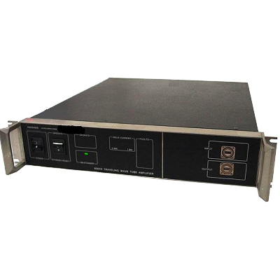
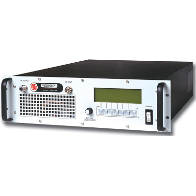
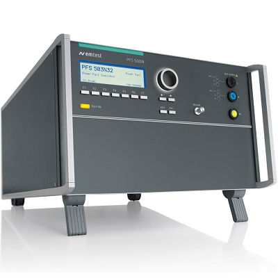
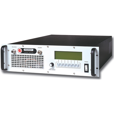
| Chassis | The Amplifier is designed for stand- alone or rack-mounted operation. The Chassis is black aluminum with a powder coat finish. The unit occupies two EIA 19-inch-wide units. | |
| Weight | 35 lbs (15.9 kg), Shipping 45 lbs (20.4 kg) | |
| AC Power | Single phase, 120 VAC, 60 Hz, 20A service; (220-240 VAC, 50-60 Hz, 10A service model available) | |
| Operating Temperature | 10°C to 50°C (50°F to 122°F), maximum output Power de-rated above 30°C (86°F).) | |
| Humidity | 70% or less, non-condensing | |
| Cooling | Forced air cooling from front to back through removable filters. | |
| Airflow | 180CFM | |
| Dimensions | 19 in. x 22.75 in. x 3.5 in. (48.3 cm x 57.8 cm x 8.9 cm) | |
| Protection | ||
| Over/Under Voltage | ± 10% from specified supply voltage amplifier is forced to Standby | |
| Over Current | Breaker protection on both main power and low voltage supplies | |
| Over Temperature | Separate output transistor, heat sink, and transformer temperature monitoring and protection | |
